Tutorial: [Godot Mode] "Action Game Maker from Scratch" Chapter 1

Chapter 1: Learn About Godot Engine and ACTION GAME MAKER

Introduction

This tutorial is designed for those who have no prior knowledge of game development, cannot program, but still want to create a full-fledged game. Here, you will learn the basics of creating games using “ACTION GAME MAKER” from the ground up.

In Chapter 1, before starting actual game development, we will cover the following foundational knowledge:

  • What kind of tool is “ACTION GAME MAKER”?
  • What kind of engine is the underlying Godot Engine?
  • Basic operation methods of Godot Engine

ACTION GAME MAKER and Godot Engine

What is ACTION GAME MAKER?

ACTION GAME MAKER is a customized version of Godot Engine, one of the “software for creating games” commonly referred to as game engines, similar to Unity and Unreal. It has been designed so that even people with no programming knowledge can use it.

What kind of engine is Godot Engine? What can it do?

Godot Engine is a game engine that has seen rapid growth in usage in recent years.

It is a versatile game engine capable of creating games of any genre, offering high-performance capabilities with a wide range of features comparable to Unity and Unreal Engine.

Games are being developed not only for PC but also for mobile devices and Nintendo Switch. For examples of games created with Godot Engine, please view the official showcase below:

As shown above, while Godot Engine is a powerful game engine capable of creating any type of game, the ability to handle programming is essential. ACTION GAME MAKER is designed to allow people who cannot program to use Godot Engine by providing a dedicated visual scripting system.

Since all 2D features of Godot Engine are available, ACTION GAME MAKER enables the creation of 2D games similar to those in the showcase.

What kind of games can be made with visual scripting?

You might be wondering: “Even if Godot is such a powerful engine, wouldn’t the games that can be made be limited if using visual scripting instead of programming?”

The visual scripting system in this product is inherited from the previous title, “Action Game Tsukuru MV.” In that previous title, due to the high flexibility of its visual scripting system, works were created in various genres, not just jump-and-run action games, but also shooting games, fighting games, puzzle games, RPGs, and more.

Furthermore, more than 60 games have been released on Nintendo Switch™.

“ACTION GAME MAKER” combines the visual scripting system inherited from the previous title “Action Game Tsukuru MV” with the advanced features of Godot.

Let’s Get Familiar with Godot Engine First

When using ACTION GAME MAKER, start by getting hands-on with the fundamental Godot Engine. Since ACTION GAME MAKER adds dedicated features to Godot Engine, its basic UI is identical to Godot Engine and can be used directly as Godot Engine.

Creating a New “Project”

When you launch ACTION GAME MAKER, a screen called a “Launcher” for managing “Projects” will appear. Think of a “Project” as a workspace for creating games.

First, create a new project by clicking “+ New” in the top-left corner.

You can enter a project name, so please input “Tutorial”. Since the project name will become the game’s name, it is recommended to choose a clear and recognizable name.

Once entered, press the “Create and Edit” button.

Projects created here are stored in the folder ~/Documents/ActionGameMaker/{ProjectName}.

Godot Concepts: “Scenes” and “Nodes”

Before starting actual operations, let’s explain the important concepts of “Scenes” and “Nodes” in Godot game development.

In Godot, you create “Scenes” and place “Nodes” within them to build games.

This might be a bit abstract, so let’s use an amusement park as an example. A “Scene” is an attraction at the amusement park, while a “Node” is a component of that attraction. For a roller coaster, the rails, pillars, and the coaster car body itself are all “Nodes”.

By placing these attractions within a “Project” (the land), a large amusement park is created.

Godot Screen Layout

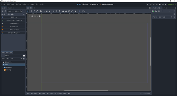
Now, the following screen should be open. This is the basic screen of Godot and ACTION GAME MAKER.

Each display area is divided as follows:

Although there are many screens arranged and it may seem complex, Godot’s screen is designed with the concept of:

“Select on the left, view in the center, and modify on the right”

Left Window

Scene: Nodes within the scene are listed. Imagine each component of the attraction being displayed one by one.

File System: All assets in the entire project are listed. In the amusement park example, think of this as a storage area where materials have been delivered to the construction site.

Center Window

Editor View: The overall view of the scene is displayed. Use this window to place components and build the attraction.

Right Window

Inspector: Information about the node selected on the left is displayed. Adjust the settings of the selected component. Imagine changing the color of a roller coaster or adjusting its maximum speed.

There are other screens not explained here, but understanding this concept first should make it easier to grasp. Now, let’s start operating.

Let’s create a “Scene”.

First, you need to create a “Node” called the “Root Node” for the “Scene”. The root node is, as its name suggests, the root (origin) of the scene. What we are creating now is an attraction, a shop, etc.; it determines the type of thing you will build.

From the top-left of the screen, select 2D Scene to create the root node.

The “Create Root Node” label has changed to Node2D. This is the root node. Since Node2D is the node that serves as the foundation for a 2D screen, selecting it means you have decided to create a 2D game.

Let’s save the scene.

In the top-left corner of the central editor screen, [Unsaved](*) is displayed. A scene is not saved just by creating it, so let’s save it first.

  1. Right-click the tab displaying [Unsaved](*).

  2. A menu will appear; select “Save Scene As…”.

  1. A window resembling an explorer will open. This displays folders and files within the project under the “File System”. Think of it as a warehouse where materials for building an amusement park are stored.

  1. By default, the filename at the bottom is node2d.tscn. If you save it as is, you may have trouble finding it later, so change the name to test_scene.tscn and save it.

There is a folder named AGMaker by default. This is where data handled by the ACTION GAME MAKER functions are stored together, so do not select any folder to avoid mixing them up.

  1. If saved successfully, [Unsaved](*) will change to the name test_scene. Also, test_scene.tscn should be displayed in the window named [File System] at the bottom-left of the screen.

Let’s Place a Node in the Scene

Next, let’s learn how to handle nodes. We’ll create a new node, place it in the game world, and customize it.

First, let’s place a rectangle in the scene.

This is the first part of “Select on the left, view in the center, change on the right”: “Select on the left”.

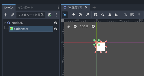
  1. Place a node that draws a rectangle into the scene. In Godot, the node used to draw a rectangle on a 2D screen is called “ColorRect”. As its name suggests—Color (color) Rectangle (rectangle)—it is a node that has the function to draw a colored rectangle.

  2. Click the “+” (Add Child Node) button in the top-left corner of the Scene window.

  1. Enter “ColorRect” in the search bar at the top and select the ColorRect node that appears.

  1. Press the “Create” button.

  2. A white rectangle has appeared in the central editor window. This is the rectangle drawn by the ColorRect node.

Let’s Launch the Game Screen in Test Play

  1. Let’s try test play right away. Click the “Run Current Scene (F6)” button in the top-right corner of the screen to start test play.

:warning: There is a similar button called “Run Project (F5)”, but it will run a different scene, so be sure to launch it using “Run Current Scene”.

  1. A new window will open. This shows how it will look when the game actually launches. If you haven’t moved the rectangle, it should be displayed in the top-left corner.

  1. Once you’ve confirmed the display, close the window using the ✕ button in the top-right corner.

If you don’t see it, close the window once and try “Run Current Scene (F6)” again. If it’s still not visible, you may have moved the rectangle. Try it again after proceeding to the next step.

Let’s try operating the Editor screen.

Currently, the square is displayed in the top-left corner, which isn’t ideal. The central Editor screen is the scene preview area, so let’s operate here to adjust how it appears.

This is the “View in the Center” part of “Select on the Left, View in the Center, Change on the Right”.

  1. First, try zooming in and out of the preview. With the Editor screen selected, roll the center mouse wheel. Rolling forward zooms in, and rolling backward zooms out. The current zoom level is displayed in the top-left corner of the Editor screen.

  1. Let’s move the position of the preview screen. While the Editor screen remains selected, try clicking the mouse wheel (middle click). The mouse icon should change to a cross-shaped arrow; keep the button pressed and move the mouse. The preview position should move.

  2. Using zoom and preview movement, ensure the thin blue square located to the bottom-right of the green and red crosshairs (this point is called the origin) is visible. This blue square represents the game screen area. The white square created with ColorRect was positioned at the top-left of the blue square, which is why it appeared there during the test play.

Let’s try operating the position of the white square.

Move the white square to the center of the game screen.

  1. Click the ColorRect node to select it.

  1. In the operation panel at the top of the Editor screen, click “Move Mode (W)” to switch modes.

  1. In this mode, you can move the position of the selected node. Click and drag with the left mouse button in the Editor screen to move the square to the center of the screen (the blue square).

  1. Again, run a test play to check how it looks. In the top-right menu, select “Run Current Scene (F6)”.

  1. If the movement was successful, the square should now appear near the center of the game screen.

Try Changing the Color of a White Rectangle (ColorRect) in the Inspector

Currently, the ColorRect node is pure white, but it has the functionality to change its color. Let’s change it to another color.

This corresponds to the “Change on the Right” part of the “Select on the Left, View in the Center, Change on the Right” workflow.

  1. Select the ColorRect node in the Scene window on the left.

  2. Look at the Inspector window on the right. You will see a list of many settings. These settings represent the functions available to the selected node. Each of these items is called a “Property.” Think of it like a roller coaster example, where adjustable items such as maximum speed or body color are displayed.

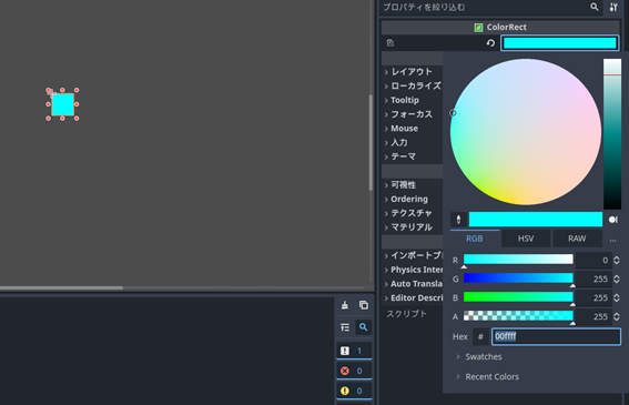
  3. The item we will change this time is clearly the “Color” property located at the very top. Click on the white rectangle next to “Color”.

  1. There are various ways to change the color, but let’s use the most intuitive default method: RGB. RGB stands for Red, Green, and Blue. Monitors express various colors by mixing these three lights.

TIPS: You might think that mixing three colors would result in black. That is true for paint, but since this involves “light,” the area where two lights overlap has double the light intensity and becomes brighter. This method of mixing colors is called “additive color mixing.”

  1. Try changing the R value from 255 to 0. As shown in the figure above, the rectangle should have turned cyan, a mixture of green and blue.

  1. As demonstrated, in Godot, you can customize nodes by changing properties (settings) in the Inspector on the right.

Let’s Add a “Node” to Depict an Image in a “Scene”

Next, let’s delve deeper into node operations.

When multiple nodes are placed, what is their positional relationship? Let’s try it out.

This time, instead of a simple rectangle, let’s place an image. We’ll use Sprite2D, a node capable of displaying images. This node is designed to display 2D images (sprites).

  1. In the Scene panel on the left, select Node2D. This is because newly added nodes will be placed as “child nodes” under the selected node. A “child node” is a node attached to its parent node. In the roller coaster example, smaller parts like wheels or seats inside the car body are child nodes. Since the Sprite2D we are setting up this time should be an independent entity, not an attachment of ColorRect, we keep Node2D selected.

  1. With Node2D selected, click the + button in the top-left corner (Add Child Node).

  2. In the search bar at the top, type “Sprite” and select the Sprite2D node.

  1. Click the “Create” button. A Sprite2D appears in the top-left view, but nothing else seems to have changed. This is because no information has been set regarding “which image to display.”

  2. Select on the left and configure on the right. Select Sprite2D in the left panel, and look at the Inspector on the right.

  1. The property that determines the displayed image is the topmost one: “Texture”.

A “Texture” is like a pattern or sticker applied to objects within the game.

  1. Select “” next to Texture. Many options will appear; click the “Load” button at the very bottom.

  1. A file selection window like the one below will open. You should see only the AGMaker folder and the icon.svg image. These two are automatically generated when creating a project with ACTION GAME MAKER.

Note that what is displayed here is the same as what appears in the “FileSystem” at the bottom-left of the screen. The file test_scene.tscn is not shown because it is unrelated to images and has been filtered out.

In Godot Engine, you can only use assets located within this “FileSystem.” You cannot directly select and use files from your computer. To work with assets, they must first be moved into the warehouse (FileSystem) of the construction site (project), like an amusement park.

  1. First, select the icon.svg already in the warehouse. An icon should appear at the top-left corner of the blue rectangle, where the red and green lines intersect. With this, you have successfully applied the icon image as a sticker to the Sprite2D node.

Learn About Node Display Order.

Select Sprite2D in the Scene window, move it using the editor’s move mode, and try overlapping it with the light blue rectangle.

The image should now appear on top of the light blue rectangle. This is because in Godot, items lower in the Scene window are displayed in front.

Let’s try changing the order in the Scene window. Click and drag Sprite2D in the Scene window to place it between ColorRect and Node2D.

The light blue rectangle now appears in front of the icon.

As shown, in Godot, the lower an item is in the Scene window, the closer it appears in the game view.

Let’s Learn the Concept of Child Nodes

Now, the term “child node” appeared in the previous explanation. Let’s try to see what kind of behavior it actually produces.

This time, let’s make Sprite2D a child node of ColorRect.

  1. Click and drag Sprite2D as before, and place it overlapping ColorRect.

  1. The display has changed as shown below. Sprite2D is now displayed slightly to the right and underneath ColorRect. This is the state of being a child node.

  1. Since the child node appears below ColorRect in the Scene window, following the rule that “lower elements in the scene are displayed in front,” Sprite2D is also displayed in front of ColorRect in the scene.

  1. Next, let’s see what happens to the child node Sprite2D when we move the parent node, ColorRect.

  2. Select the ColorRect node in the Scene view on the left, and switch the central editor view to Move mode.

  3. If it is correctly set as a child node, moving the ColorRect node should cause Sprite2D to move along with it.

  1. By making it a child node, it becomes possible to manage Sprite2D as an accessory of ColorRect and operate them together like this.

Chapter 1 Review

Now that we have learned the basic concepts and operations of Godot, in Chapter 1, we learned the following fundamental points through creating and manipulating nodes:

“In Godot, games are made by placing nodes within a scene”

“Select on the left, view in the center, and modify on the right”

“Nodes lower in the Scene window appear closer to the front in the game view”

Next, we will finally start making games functional using “scripts,” allowing them to be enjoyed like rides on an attraction. However, in Godot Engine, programming skills are essential. To achieve a state that can truly be called a game, it is necessary to gradually learn programming from the basics, which requires a significant amount of time.

But don’t worry! With ACTION GAME MAKER’s visual scripting, you can create games immediately without any prior learning.

ACTION GAME MAKER exists for those who don’t understand programming but want to create games with Godot.

In Chapter 2, let’s learn ACTION GAME MAKER’s visual scripting.