Tutorial: "Getting Started with ACTION GAME MAKER from Scratch" — Chapter 1

Chapter 1: Understanding the Godot Engine and ACTION GAME MAKER

Introduction

This tutorial is designed for users who have no prior game development experience or programming skills but still wish to create a complete game! You will learn how to use ACTION GAME MAKER step by step, starting from the basics.

In Chapter 1, before diving into actual game development, you will learn some essential background knowledge:

  • What exactly is ACTION GAME MAKER?
  • What is the Godot Engine, the foundation of ACTION GAME MAKER?
  • How to use the basic features of the Godot Engine?
2 Likes

ACTION GAME MAKER and Godot Engine

What is ACTION GAME MAKER?

ACTION GAME MAKER is a tool custom-developed based on the Godot Engine.
Like Unity and Unreal, Godot Engine is one of the major “game development software tools,” commonly referred to as a game engine.

ACTION GAME MAKER has been specially optimized so that even people with absolutely no programming knowledge can use it to create games.


What is Godot Engine? What can it do?

Godot Engine is a game engine that has rapidly gained popularity in recent years.

It is a general-purpose game engine with powerful features comparable to Unity and Unreal Engine, capable of creating almost any type of game.

With Godot, you can not only develop PC games but also smartphone games, and even create titles for platforms like Nintendo Switch.
To see examples of games already made with Godot, check out the official showcase video below.

:backhand_index_pointing_right: Official Showcase

Godot Engine is an extremely flexible tool that can realize nearly any game idea.
However, typically, programming knowledge is required to fully utilize its capabilities.

This is precisely where ACTION GAME MAKER adds value.
By providing a dedicated visual scripting system, it enables users without programming experience to fully harness the power of the Godot Engine.

Since all of Godot’s 2D features are fully accessible, you can create 2D games in ACTION GAME MAKER that match the quality of those shown in the official showcase.


What types of games can you create using visual scripting?

You might be concerned:
“Even if Godot is powerful, will using visual scripting limit the types of games I can make compared to writing actual code?”

The visual scripting system in ACTION GAME MAKER is inherited from its predecessor, Action Game Maker MV.
Thanks to its high flexibility, creators have developed not only platformers but also shooters, fighting games, puzzle games, RPGs, and many other genres.

In fact, over 60 games created using the previous system have been officially released on Nintendo Switch™.

:backhand_index_pointing_right: Watch the showcase video

ACTION GAME MAKER is an evolved tool built upon this proven visual scripting system, enhanced with Godot’s advanced features.

First, Get Familiar with the Godot Engine

Before using ACTION GAME MAKER, let’s first get hands-on experience with the basics of the Godot Engine.
Since ACTION GAME MAKER is essentially an extension built on top of the Godot Engine, its core UI is identical, and its operation methods are consistent with standard Godot.


Creating a New Project

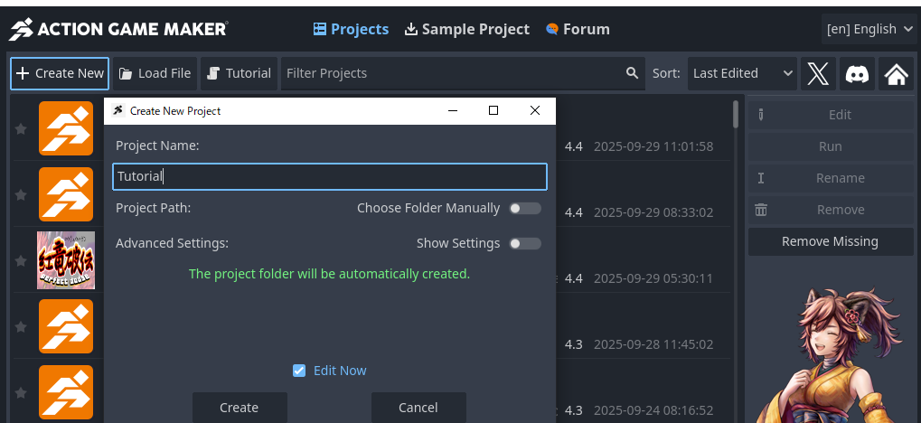
After launching ACTION GAME MAKER, you’ll see an interface called the Launcher.
Here, you can manage your projects.
Think of a “project” as the workspace for developing a game.

  1. Click + New Project in the upper-left corner.
  2. Enter a project name — for this example, we’ll use Tutorial.
    • Note: The project name will also become the game’s name, so it’s recommended to use a clear and meaningful name.
  3. Click the Create and Edit button.

Projects created here will be saved to the following folder:
UserName\\Documents\\ActionGameMaker\\{ProjectName}


Core Godot Concepts: “Scenes” and “Nodes”

Before diving into the editor, let’s understand two fundamental concepts in Godot game development: Scenes and Nodes.

In Godot, you build games by creating scenes and placing nodes within them.

This may sound abstract, so let’s use an analogy: a theme park.

  • A Scene is like a single ride in the theme park.
  • A Node represents the individual components that make up that ride.

For example, in a roller coaster ride, the tracks, supports, and roller coaster cars are all Nodes.

By placing one ride (scene) after another in your project, you gradually construct the entire theme park —
just as you build a complete game step by step.

Godot Interface Layout

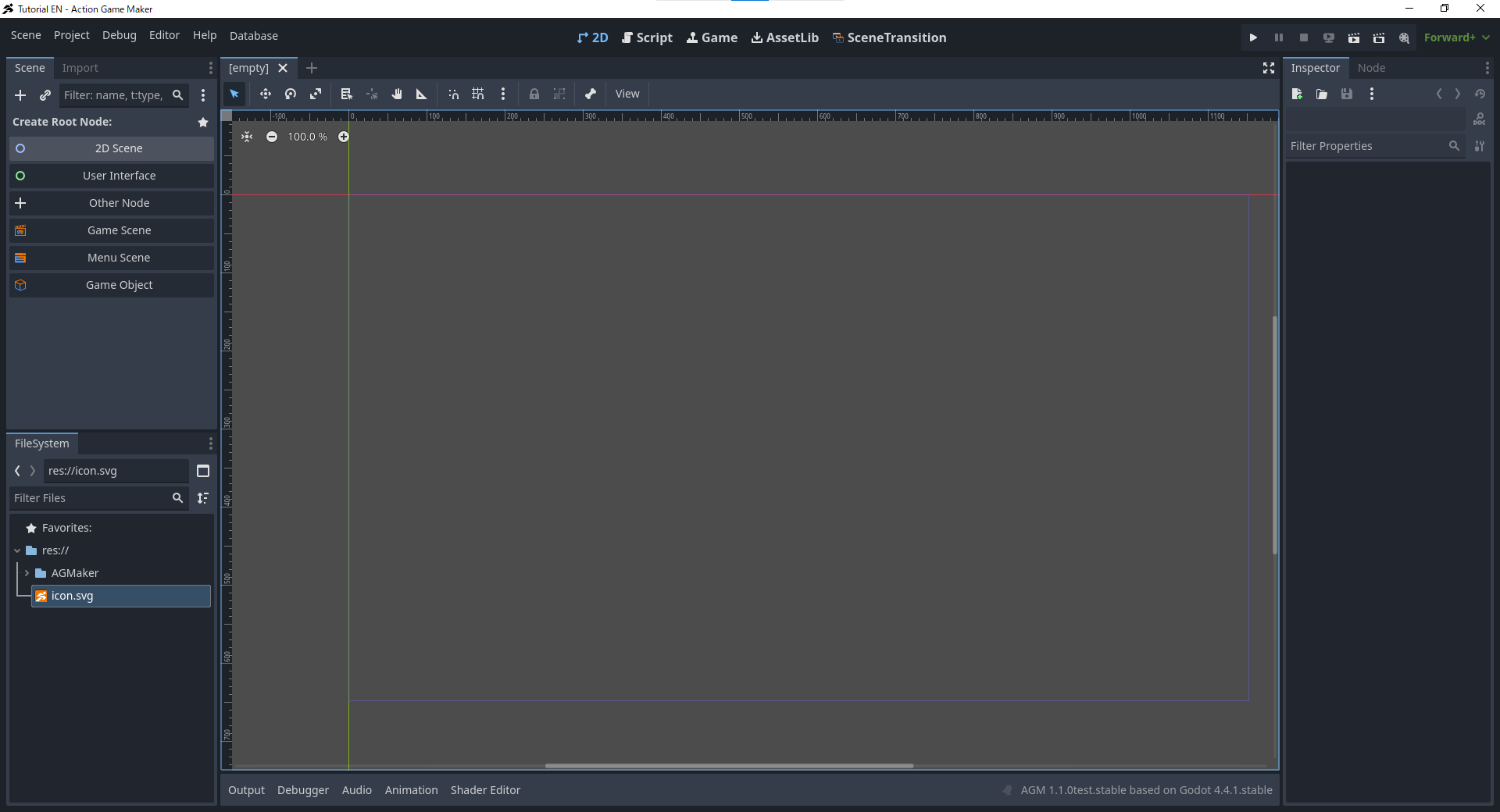
At this point, you should see a screen similar to the one shown below. This is the basic interface of Godot, and also the basic interface of ACTION GAME MAKER.


Main Interface Structure

The entire interface is divided into multiple areas, each serving its own purpose.

At first glance, it may seem like there are many panels and the structure is somewhat complex, but Godot’s interface design follows a very simple principle:

“Select on the left, view in the center, adjust on the right.”


Left Panel

  • Scene:
    Displays a list of all nodes contained in the current scene.

    • Using an amusement park analogy, this is like viewing which components make up a particular ride.
  • FileSystem:
    Displays all available assets and resources in the entire project.

    • In the amusement park analogy, this corresponds to a warehouse area storing various construction materials, ready for use at any time.

Central Panel

  • Editor View:
    Displays the overall view of the entire scene.
    • Here, you will place and arrange various components to gradually build a complete ride.

Right Panel

  • Inspector:
    Displays detailed information about the node selected in the Scene panel.
    • Here, you can adjust various properties of the component—for example, changing the color of a roller coaster or modifying its maximum speed.

There are other panels in the interface, but for now, remembering this basic structure will make it easier to understand and operate.

Next, let’s start performing some hands-on operations.

Creating a Scene

First, you need to create a Root Node for your scene.
As the name suggests, the root node serves as the foundation (“root”) of the scene. It determines the type of content you will build next—for example, a ride, a shop, or something else.

  1. In the top-left corner of the screen, click Create Root Node, then select 2D Scene.

At this point, the Create Root Node label will change to Node2D.
This is your root node.

Since Node2D is the base node for 2D scenes, this also means you’ve made a decision:
“I’m going to make a 2D game.”


Saving the Scene

In the top-left corner of the editor window, you’ll see a tab labeled unsaved.
Simply creating a scene does not automatically save it, so let’s save it now.

  1. Right-click the tab labeled unsaved.

  2. From the menu, select Save Scene As….

  3. A file browser window will open. This is the FileSystem, which displays folders and files in your project.

    • Think of it as a warehouse storing all the building materials for your amusement park.
  4. The default filename is node2d.tscn. If you keep this name, it may be hard to find later.
    Change the filename to test_scene.tscn, then save.

    • You’ll see a folder named AGMaker.
      This folder is reserved for internal data used by ACTION GAME MAKER—do not select it.
      Simply save the scene at the current level.
  5. If the save is successful, the unsaved label on the tab will change to test_scene,
    and you’ll also see test_scene.tscn appear in the list within the FileSystem panel at the bottom-left corner.

Adding Nodes to the Scene

Next, let’s learn how to manipulate Nodes.
You will create a new node, place it in the game world, and customize it.

First, let’s place a Rectangle in the scene.

This corresponds to the first step of the fundamental principle mentioned earlier:
“Select on the left, view in the center, adjust on the right.”


Adding a Rectangle (ColorRect Node)

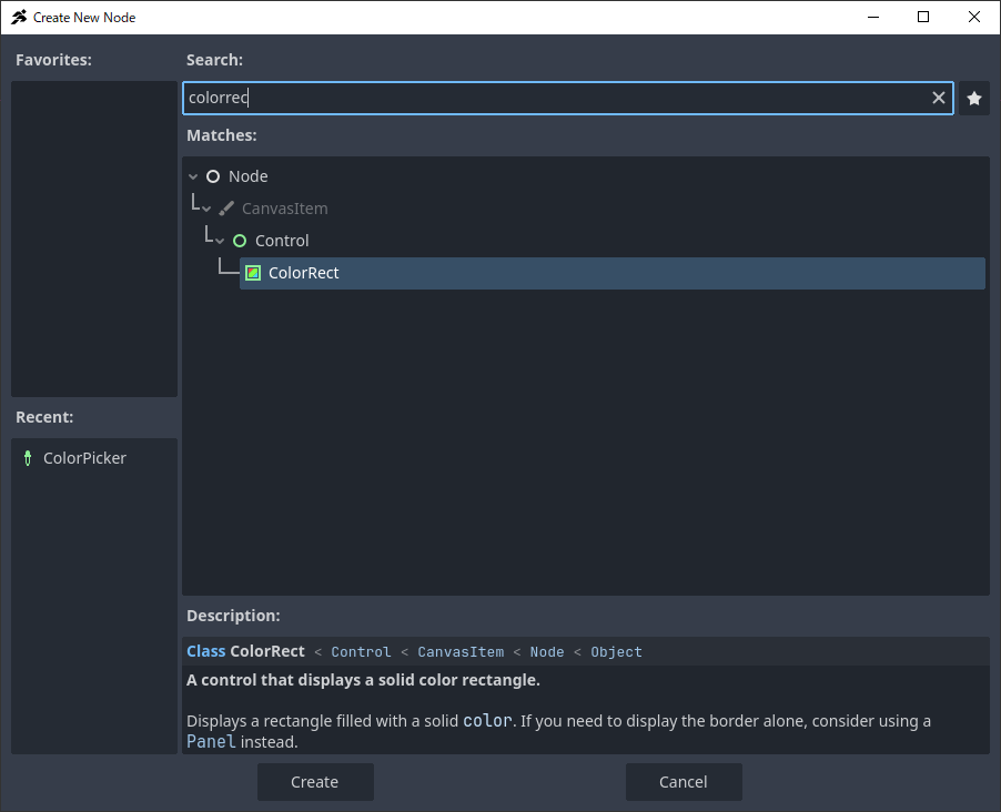
  1. Add a node to the scene for drawing a rectangle.

    • In Godot, the node used to draw rectangles on a 2D canvas is called ColorRect.
    • As the name suggests (Color + Rectangle), this node draws a colored rectangle.
  2. In the top-left Scene panel, click the “+” (Add Child Node) button.

  1. In the search bar at the top, type ColorRect, then select the displayed node.

  1. Click the Create button.

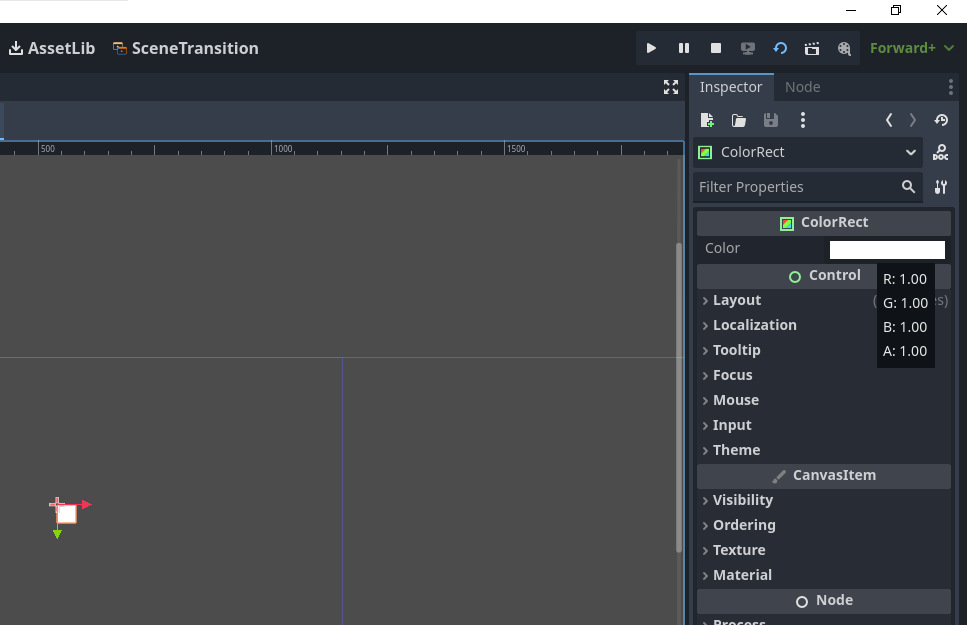
  2. In the central editor window, a pure white rectangle will appear.

    • This is the rectangle drawn by the ColorRect node.


Testing the Scene

  1. Let’s immediately test-run this scene.

    • In the top-right corner, click the “Run Current Scene (F6)” button.

:warning: Please do not use “Run Project (F5)”, as it will launch other scenes.
Here, be sure to use “Run Current Scene”.

  1. A new window will open.

    • This window displays the actual in-game visual effect.
    • If you haven’t modified the rectangle’s position, it should appear in the top-left corner of the screen.

  1. After confirming the display is correct, click the X button in the top-right corner to close the window.

:backhand_index_pointing_right: If nothing is displayed:

  • After closing the window, run the scene again using Run Current Scene (F6).
  • If it still doesn’t display, you may have accidentally moved the rectangle.
    Continue with the following steps and verify again later.

Try Manipulating the Editor View

Currently, the white rectangle is fixed in the top-left corner of the screen, which doesn’t look ideal.
The Editor View is a preview of the scene, so let’s first adjust how it is displayed here.

This corresponds to the second step in the basic principle:
“Select on the left, view in the center, adjust on the right.”
Specifically, the “view in the center” part.


Zoom the View

  1. First, try zooming in and out of the preview.

    • With the Editor View selected, scroll your mouse wheel.
    • Scroll forward to zoom in, backward to zoom out.
    • The current zoom level will be displayed in the top-left corner of the Editor View.

Move the Preview View

  1. Next, move the position of the preview.

    • Keep the Editor View selected, and press and hold the middle mouse button (scroll wheel).
    • The mouse pointer will change to a cross-shaped arrow.
    • While holding the middle button, drag the mouse to move the preview.
  2. Combine zooming and moving to adjust the view so that the blue rectangle (game screen area)
    is centered around the green and red crosshairs (this point is called the “origin”).

  • Currently, the white rectangle created by the ColorRect node is located at the top-left corner of the blue area,
    which is why it appears in the top-left corner during testing.

Move the White Rectangle

Next, let’s move the white rectangle to the center of the game screen.

  1. Click the ColorRect node to select it.

  2. At the top of the editor, switch to Move Mode (W).

  1. In this mode, you can move the position of the selected node.

    • In the Editor View, click and drag the rectangle with the left mouse button
      to move it to the center of the blue rectangle (game screen).

  1. Click Run Current Scene (F6) in the top-right corner to test-run again.

  2. If the movement was successful, the rectangle should now appear near the center of the game screen.

Changing the Color of the White Rectangle (ColorRect) in the Inspector

Currently, the ColorRect node is still pure white.
However, one of the functions of this node is to allow you to freely change its color.
Let’s now try changing it to another color.

This corresponds exactly to the final step in the basic principle:
“Select on the left, view in the middle, adjust on the right.”


Steps

  1. In the Scene panel on the left, select the ColorRect node.

  1. Look at the Inspector panel on the right—you’ll see many settings.

    • These settings represent the various functions available for the currently selected node.
    • Each setting is called a Property.
    • In the roller coaster analogy, these properties are like adjustable parameters such as maximum speed or car color.
  2. The property we want to modify is easy to find:
    At the top, locate Color.

    • Click the small white rectangle next to it.

  1. A color selection window will pop up.
    There are many ways to set the color, but the simplest is the default RGB mode.

  • RGB stands for Red, Green, Blue.
  • Monitors display all colors by mixing light of these three colors.

Tip:
You might wonder: “Shouldn’t mixing three colors result in black?”

  • That’s true for pigments, but here we’re dealing with light.
  • When two lights overlap, their brightness adds up, making the result brighter.
  • This mixing method is called Additive Color Mixing.

  1. As a test, change the R (Red) value from 255 to 0.

  • As shown in the image above, the rectangle will turn into Cyan, a mixture of green and blue.

  1. Using this method, you can adjust various Properties of the node in the Inspector on the right,
    allowing you to freely customize the node’s appearance and behavior.

Adding a Node to Draw an Image in the Scene

Next, we will delve deeper into how to use Nodes.

What happens when you place multiple nodes in a scene?
Let’s try it out ourselves.

This time, instead of placing just a rectangle, we will place an image.
To do this, we will use Sprite2D — a node designed to display 2D images (Sprites).


Adding a Sprite2D Node

  1. In the Scene panel on the left, select Node2D.

  • This step is crucial because newly added nodes become children of the currently selected node.
  • A Child Node refers to a node that belongs to a parent node.
  • Using a roller coaster as an analogy, components like wheels and seats (child nodes) belong to the roller coaster car (parent node).
  • Since we don’t want Sprite2D to become a child of ColorRect, we select Node2D here.
  1. With Node2D selected, click the “+” (Add Child Node) button in the top-left corner.

  1. In the search bar, type Sprite, then select Sprite2D.

  1. Click the Create button.
  • At this point, you’ll see Sprite2D has been added in the Scene panel…
  • But visually, nothing seems to have changed on the screen.
  • This is because we haven’t yet told it which image to display.


Setting the Texture

  1. Following the principle of “Select on the left, adjust on the right”, select Sprite2D in the Scene panel,
    then look at the Inspector panel on the right.

  2. The property we need is at the top: Texture.

  • Texture can be thought of as a sticker or pattern applied to a game object.
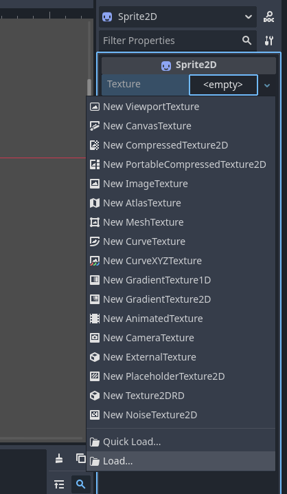
  1. Click the box next to Texture labeled .
  • A menu will appear; scroll down and click Load at the bottom.

  1. A file selection window will open. You should see only two items:
  • A folder named AGMaker
  • An image file named icon.svg

These are automatically generated when creating an ACTION GAME MAKER project.

:warning: Note:
The content shown here is identical to what appears in the FileSystem panel at the bottom-left.

  • Files like test_scene.tscn won’t appear here
    because they are not image files and have been filtered out.

In the Godot engine, you can only use assets stored in the project’s FileSystem.

  • You cannot directly load files from arbitrary locations on your computer.
  • Using the amusement park analogy, assets must first be placed in the project’s warehouse (FileSystem) before they can be used.
  1. Now, select icon.svg.

  • You should see the icon displayed at the top-left corner of the blue rectangle,
    which is where the red and green crosshairs intersect.
  • Congratulations — you’ve successfully applied an image (icon.svg) as a Texture
    to the Sprite2D node.

Understanding Node Drawing Order

In the Scene panel, select Sprite2D.
Then, using Move Mode in the editor view,
drag it to overlap with the light blue rectangle.

At this point, you should see the image displayed above the light blue rectangle.
This is because, in Godot, nodes positioned lower in the Scene panel are drawn in front.


Changing the Drawing Order

Next, let’s actually change the order and see what happens:

  1. In the Scene panel, click and drag Sprite2D.

  1. Place it between ColorRect and Node2D.

Now, the light blue rectangle will appear in front of the icon.


Important Rule

In Godot:

“The lower a node’s position is in the Scene panel, the more prominently it appears in the game.”

Understanding the Concept of Child Nodes

Previously, we mentioned a concept called Child Node.
Now, let’s explore what it actually means through hands-on practice.

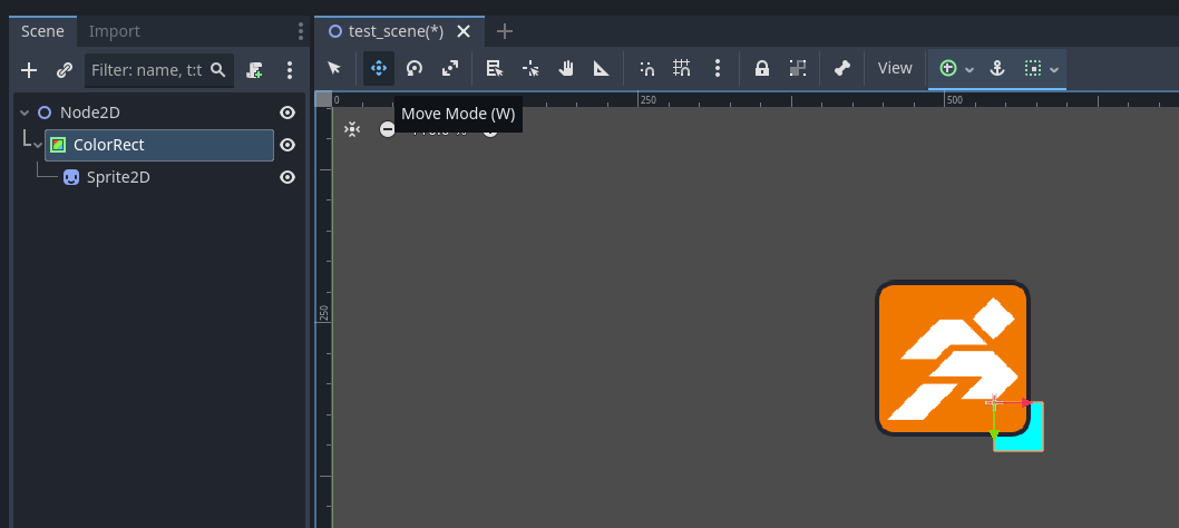
This time, we will set Sprite2D as a child node of ColorRect.


Steps to Follow

  1. In the Scene panel, click and drag Sprite2D,
    then drop it onto ColorRect.

  1. The display will change as follows:
  • Sprite2D will indent slightly to the right in the Scene panel and appear beneath ColorRect.
  • This indicates that it has become a child node of ColorRect.

  1. Since child nodes are displayed beneath their parent nodes,
    and combining this with the previously mentioned rule:
    “Nodes positioned lower in the Scene panel are drawn in front,”
    Sprite2D will still appear in front of ColorRect in the scene.

  2. Next, let’s test what happens when we move the Parent Node.

  3. In the Scene panel, select the ColorRect node,
    then switch to Move Mode in the editor view.

  1. If configured correctly, when you move ColorRect,
    Sprite2D will move along with it.

  2. By setting a node as a child node, you can group it with its parent and manipulate them together.
    In this example, Sprite2D acts like an attached component of ColorRect.

Chapter 1 Review

Now, you have learned the basic concepts and fundamental operations of Godot.
In Chapter 1, by creating and manipulating nodes, you mastered the following key points:

  • In Godot, games are built by placing nodes within a scene.

  • The interface follows the rule: “Select on the left, view in the center, adjust on the right.”

  • In the Scene panel, nodes positioned lower in the list appear in front of others in the game view.

Next, we finally enter the stage where things truly “start moving like a game” —
that is, using something called scripts to make your amusement park ride genuinely playable.

However, in the Godot engine, writing scripts typically requires programming knowledge.
Learning programming from scratch and gradually advancing your project to the level of a “real game” often takes considerable time.

But don’t worry!
With ACTION GAME MAKER’s visual scripting system,
you can start making games immediately — without any prior programming experience.

This is precisely the purpose of ACTION GAME MAKER:
To enable people without programming skills to create games using Godot.


Preview of Next Chapter: Chapter 2

In Chapter 2, we will officially begin learning
how to use ACTION GAME MAKER’s Visual Scripting.

:backhand_index_pointing_right: Click here to continue reading