Tutorial: "Getting Started with ACTION GAME MAKER from Scratch"—Chapter 2

Tutorial: “Getting Started with ACTION GAME MAKER” — Chapter 2

Chapter 2: Let’s Create a Simple Level!

Chapter 2 Objectives

Starting from here, we will officially begin developing an action shooter game.

In this chapter, we will gradually complete the creation of a simple level, in which:

  • The player character can walk and jump.

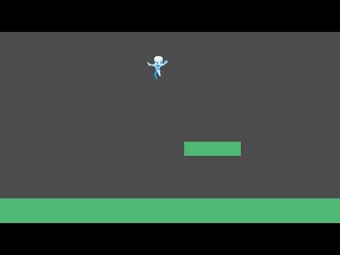
After completing this chapter, you will be able to create video content similar to the example below.


Creation Process

  1. First, we need to create a scene for the level itself.

  2. Then, place platforms within this level where the character can walk and jump.

  3. Next, we will create a character scene and use Visual Scripting to add basic behaviors such as movement for the character.

Learning “Game Scene” and “Game Object”

In Chapter 1, we completed all operations using only the built-in features of the Godot Engine.
Starting from here, we will officially use the additional features provided by ACTION GAME MAKER to build our game.

In the Godot Engine, you typically need to add nodes one by one under the root node
to create characters, levels, and other elements.
However, this approach can often be time-consuming.

To address this, ACTION GAME MAKER provides two main preset scene types
to make the game development process more efficient:

  • Game Scene

    • A Game Scene is used to create levels or stages.
  • Game Object

    • A Game Object is used for elements such as players, enemies, and items.

In ACTION GAME MAKER, you will gradually build your entire game
by placing Game Objects into Game Scenes.


How to Identify Features Added by ACTION GAME MAKER

Features added by ACTION GAME MAKER —
such as Game Scene and Game Object
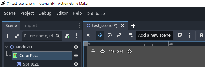
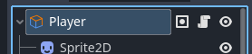
are marked with dual-color icons combining blue and orange.

When you see nodes or buttons with this dual-color icon,
you can identify them as exclusive features of ACTION GAME MAKER.

In contrast, native Godot Engine nodes typically use single-color icons
(e.g., white, blue, green, etc.),
although there are a few exceptions that use multiple colors.

Creating the “Game Scene”

Next, let’s create a Game Scene.


Steps

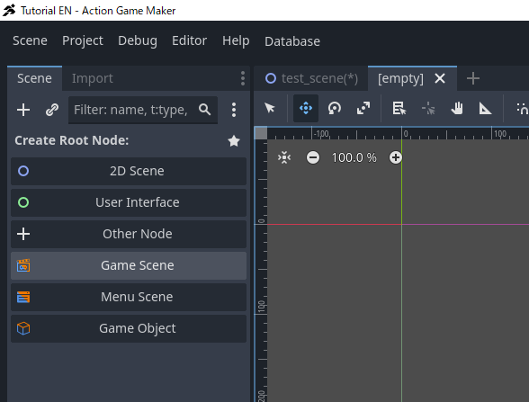
  1. In the Scene tab, click the “+” (Add New Scene) button.

  1. In the pop-up Scene window, under Create Root Node, select Game Scene.

  1. The Scene window will automatically generate numerous nodes.
    These are the preset nodes that constitute the Game Scene.

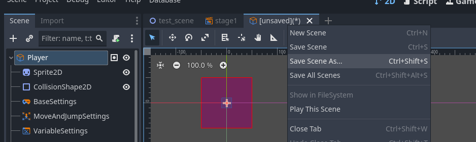
  1. Since this is a newly created scene, let’s save it first.

    • Right-click the \[unsaved\] tab, then select Save Scene As.

  1. As this is a stage (level) scene, save it as stage1.tscn.


Structure of the Game Scene

You may have noticed that many nodes have suddenly appeared—
So, what exactly does each of them do?

In ACTION GAME MAKER, the Game Scene is organized using the concept of “Layers”.

Layers can represent depth, similar to the structure of a theater stage:

  • Background Layer: Located farthest away, used to display background scenery.
  • Character Layer: Positioned in the middle, serving as the space where characters move and perform.
  • Foreground Layer: Located closest to the viewer, used to place props nearest to the audience.

When viewed from a “camera positioned in front,”
these layers together form a complete scene within the game.

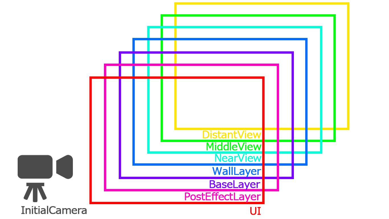
ACTION GAME MAKER provides 7 default layers.
Each layer has a distinct name and icon, with slightly different functions,
and they are stacked in the order shown in the image below.

By default, each layer already contains the minimum required preset nodes,
and the entire scene also includes a camera for capturing the scene.


Difference Between “SceneLayer” Nodes and “UI” / “PostEffectLayer” Nodes

If you closely observe the icons of these 7 layers, you’ll notice they can be roughly divided into two categories:

  1. The 5 layers from Base to DistantView
    — These are all child nodes of the SceneLayer.

  2. The UI and PostEffectLayer layers.

The difference between them is:

  • SceneLayer nodes represent areas with spatial depth;
    their displayed content changes as the camera position changes.

  • UI and PostEffectLayer nodes
    remain visible on screen regardless of camera movement.

To understand this using the theater analogy:

  • The stage itself is the SceneLayer.
  • The filters placed in front of the camera lens are the UI and PostEffectLayer.

Setting the “Initial Scene”

In ACTION GAME MAKER, scenes are managed through a dedicated Scene Transition system.
This system uses an operation method similar to visual scripting to define the connections between scenes.

First, we need to set the scene we just created as the Initial Scene
the scene that will be displayed first when the game starts.


Steps

  1. At the top center of the screen, switch the editor mode to SceneTransition.

  • This button switches the content displayed in the central editor window.
  1. An empty grid will appear on the screen.
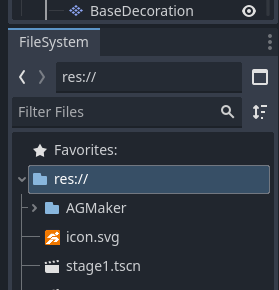
  • From the FileSystem panel in the bottom-left corner,
    drag the previously saved scene stage1.tscn onto this grid.

  1. If you see stage1.tscn appear in the grid, the setup is complete.

  1. Click the button at the top center again to switch back to 2D mode and return to the previous editing view.

image

  • This ensures that stage1 will be displayed as the first scene when the game starts.

Note: What happens if no initial scene is set?

In ACTION GAME MAKER, there is a special scene called core.tscn
that always runs in the background.

Typically, core.tscn is responsible for loading and displaying the game scene you specify.

If no initial scene is set, only core.tscn will be displayed on screen—
meaning the game will start with a blank screen.

Setting Up Tiles

Now, let’s create platforms for our level.

We need a ground and some floating platforms that the player can jump onto.
There are many ways to create platforms using different nodes, but since we’re designing a large, varied level, we’ll use a node specifically designed for this purpose: Tile.

Tiles are like floor tiles—small images that can be repeated in a grid to construct larger structures such as platforms.


Importing Tile Images into the FileSystem

First, we need to prepare the tile image.

Please right-click and save the image provided below.

tile

As explained in Chapter 1, the Godot engine can only use assets placed within the project’s FileSystem.
Think of the FileSystem as a warehouse—materials for your amusement park must be placed in the warehouse before they can be used.

Importing is simple:
Just drag and drop the file into the editor.

  1. Keep the folder on your computer containing the downloaded image open.

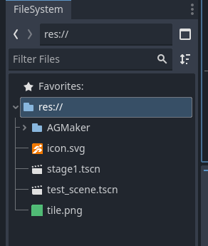
  2. In the editor, navigate to the FileSystem panel in the bottom-left corner and select res://.

  • The imported file will be placed in the currently selected folder.
  1. Drag tile.png from your computer’s folder into the editor window.


Choosing the Tile Layer

Next, we need to decide which Layer to place our tiles on.
We’ll use BaseLayer, the default layer for ground tiles.

Expand BaseLayer, and you’ll see three nodes:
Base, BaseDecoration, BaseCover.
These are all TileMapLayer nodes, just with different names.

Why prepare three similar nodes?

  • To allow overlapping tiles, creating depth and layering.
  • For example, you might want to place a torch on top of a ground tile.
  • If there were only one layer, placing the torch would cover the ground tile.
  • With multiple layers, both ground and decorations can be displayed simultaneously.

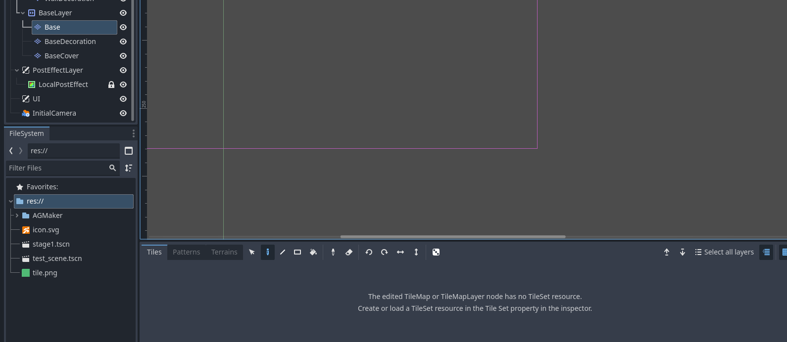
Now, select the node named Base to place your tiles.

At the bottom of the screen, you’ll see a message like:
“No TileSet found. Please create a TileSet in the Inspector.”


Creating a TileSet

A TileSet defines the basic properties of the tiles used by this TileMapLayer, such as:

  • The size and shape of each tile
  • Whether it can collide with characters or be passed through

Our prepared tile image is a 48×48 pixel square.
Since it will serve as a platform for the player to stand on, collision must be enabled.

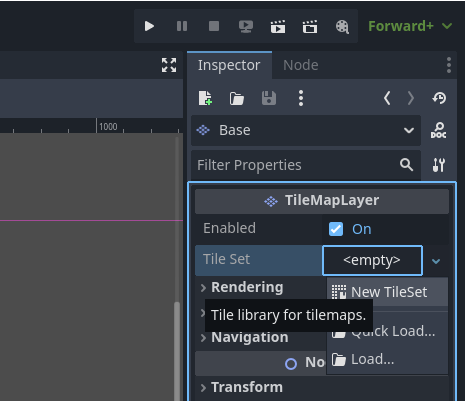
  1. In the Inspector, locate TileSet,
    click , and select New TileSet.

  1. Next, configure the TileSet properties as follows:
  • Tile Shape: Square
  • Tile Size: x = 48 px, y = 48 px

  1. Expand Physics Layers, and click + Add Element.

  1. Leave Collision Layer / Collision Mask at their default settings.
  • If your Inspector displays something like Physics Layer 0 as shown in the example,
    your TileSet’s basic setup is complete.


Note: Collision Layer and Collision Mask

In Godot, collisions are determined by two settings:

  • Collision Layer: The group this node belongs to
  • Collision Mask: Which groups this node can collide with

We’ll explain this mechanism in more detail in Chapter 3.


Configuring Tile Content

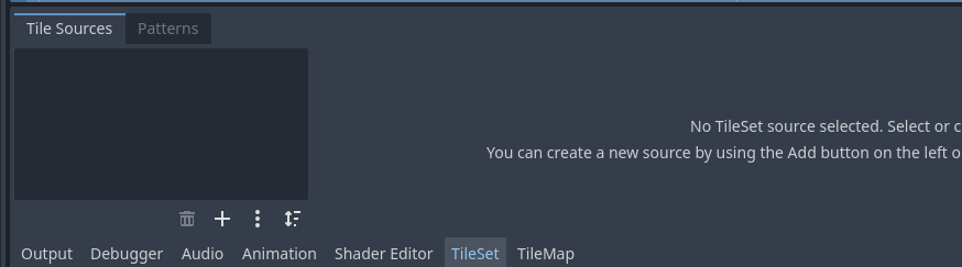
After creating the TileSet, the bottom message will change to something like:
“No source for TileSet”.

This means we still need to assign an image to the tiles,
and set up the collision shape (ground/walls).

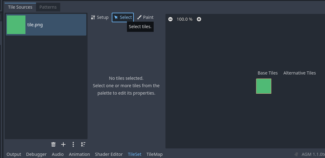
  1. In the bottom panel, switch the tab from TileMap to TileSet.

  1. From the FileSystem panel, drag tile.png into the black area on the left side of the TileSet editor.

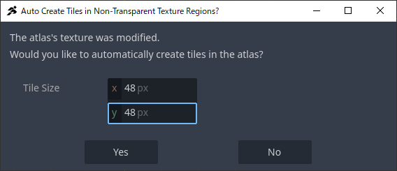
  1. A new window will appear.
    Since our tile is a 48×48 square, set
    Tile Size: x = 48, y = 48, then click Yes.

  1. You’ll then be asked:
    “Set the Tile Format to Auto Tile?”
    Select No.


Note: What Are Atlas and Auto Tile?

Atlas refers to combining multiple small images (like ground, walls, slopes)
into a single large image.
The engine loads just one large image and slices it into multiple tiles, improving efficiency.

Auto Tile is a unique feature of ACTION GAME MAKER.
It automatically organizes tile atlases in specific formats, but we won’t use this feature this time.


Adding Collision Shapes to Tiles

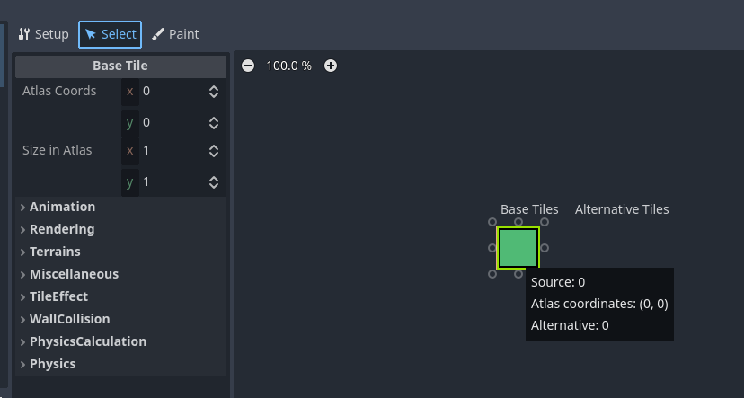
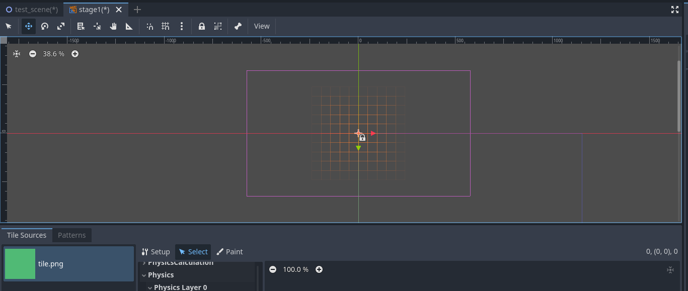
  1. In the TileSet editor, switch to the Select tab at the top.

  • This tab allows detailed configuration of individual tiles.
  1. Click the tile image on the right to select it.
  • The panel below will switch to display the properties of this tile.

  1. Scroll down and expand Physics > Physics Layer 0.

  • This is the physics layer we created earlier.
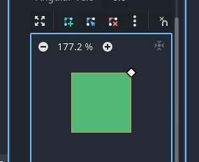
  1. Click the Add Polygon Tool (square icon with a “+”).

  • This tool adds vertices to draw polygons.
  • A polygon is a shape formed by connecting multiple points.
  1. Click the top-right corner of the green square; a diamond-shaped point will appear.

  1. Proceed clockwise, repeating the same action for the bottom-right, bottom-left, and top-left corners.

  1. Finally, click the first point you placed (top-right corner) again.

  • The tile will turn orange, indicating the entire square has been set as a collision area.

Troubleshooting Common Issues

  • If points are misplaced:
    Use the Edit Point Tool (square icon with an arrow) to move points.

  • If you accidentally added too many points:
    Use the Delete Point Tool (square icon with an “X”) to remove extra points.


:white_check_mark: You’ve now successfully completed the following steps:
Imported the tile image, created a TileSet, assigned the image, and set up collision.
This tile is now ready to be used as a platform for your character to stand on.
Placing Tiles

Now that the tiles are ready, let’s place them into the level.
Our goal is to create a ground and some platforms within the camera’s visible area.


Steps

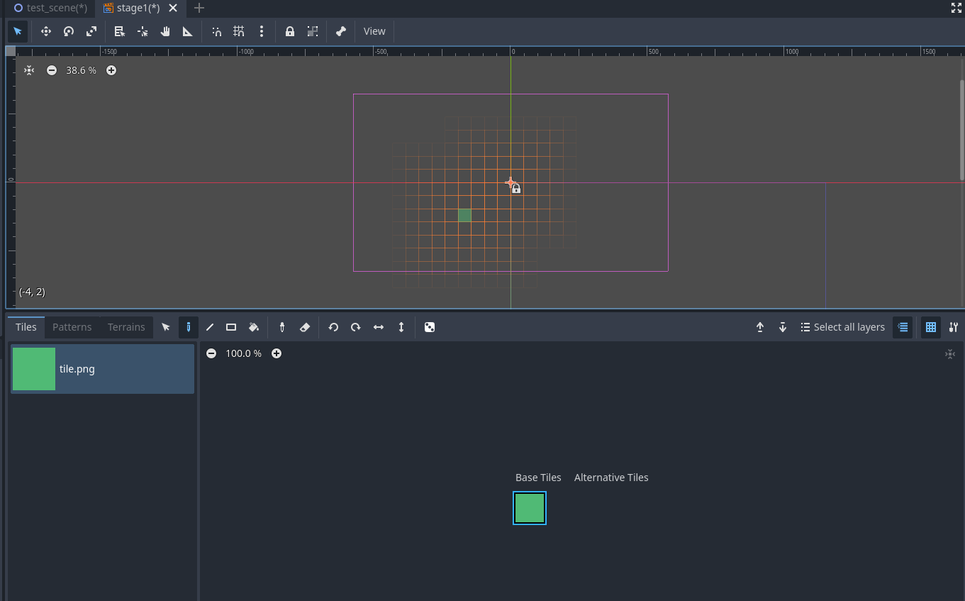
  1. Look at the Editor View in the center of the screen.

    • You should see a rectangle outlined in thin purple lines,
      centered at the point where the red and green axis lines intersect.
    • This purple rectangle represents the camera’s visible area.
    • First, adjust the view so that the entire camera area is fully visible.

  2. In the Editor View, hold down the middle mouse button (scroll wheel).

    • The mouse pointer will change to a cross-shaped arrow.
    • While holding the middle button, drag the mouse to pan the view until the purple rectangle is fully visible.
    • If the purple rectangle appears too small or too large,
      use the mouse wheel to zoom until it fits appropriately in the view.
  3. In the bottom panel, switch the tab back to TileMap.

    • The tiles you created earlier should now be available for use.

  4. On the right side of the bottom panel, click a tile to select it.

  5. Move your mouse into the Editor View;
    the tile will appear as a preview beneath the mouse pointer.

    • Left-click: Place the tile
    • Right-click: Delete the tile

    • If you cannot place tiles,
      the editor may still be in Move Mode.
      Switch back to Select Mode.

  6. Draw the ground and platforms following the example below.

    • You don’t need to replicate it exactly,
      but if platforms are placed too high, the character may not be able to jump to them.

Confirm with Test Run

Next, let’s verify the result in-game.

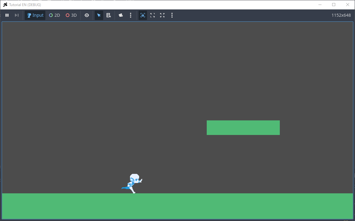
  • Click Run Project (F5) in the top-right menu.
  • If configured correctly, you should see the ground and platforms made of tiles displayed properly.


Troubleshooting Checklist

If tiles are not displayed as expected, check the following:

  • Are the tiles placed within the purple rectangle (camera’s visible area)?
  • In SceneTransition,
    is the Initial Scene correctly set to stage1.tscn?

Setting Up Input Mapping

Now that we have prepared a simple level,
the next step is typically to create the player character.

However, before that, let’s configure the Input Map.

The purpose of the Input Map is to define:

  • “When this button or key is pressed, perform this action.”

In this tutorial, we will create a relatively simple action shooter game,
so for now, we only need the most basic actions.

This time, we will create only the following four actions:

  • Attack
  • Jump
  • Move Right
  • Move Left

(You can later add actions such as sliding, weapon switching, climbing ladders, etc.,
but for now, we’ll start with the most fundamental and essential controls.)


Steps

  1. In the Project menu at the top-left corner, open Project Settings.

  1. A new window will appear.
    Switch the tab at the top from General to Input Map.

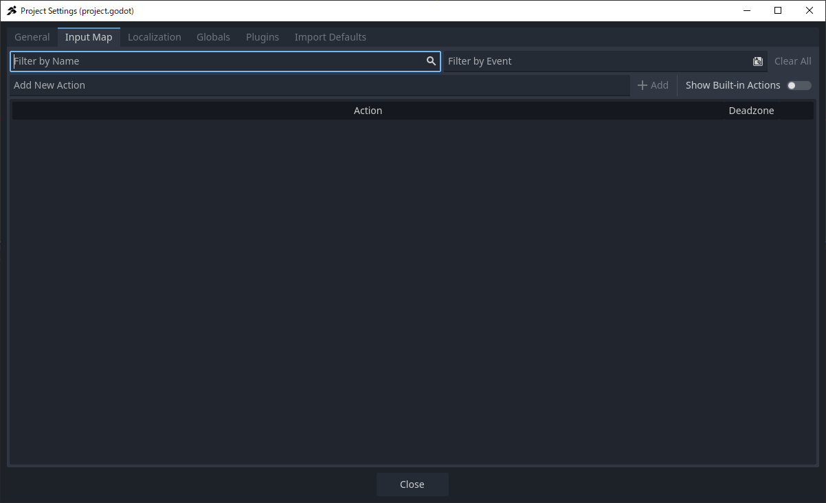
  1. In the input field labeled “Add New Action”, enter the action name.

  2. Type Right, then click the + Add button on the right.

  1. Using the same method, continue adding the following actions:
  • Left
  • Jump
  • Attack

If your list looks like the example below, you’ve done it correctly.

  1. Next, on the far right of the Right row, click the “+” (Add Event) button.

  1. A window titled “Add Event to Right” will appear.
    Press the → (Right Arrow Key) on your keyboard.

  1. If the window displays
    Right or Right (Physical) or Right (Unicode),
    the setup is successful. Click OK.

  2. Repeat the same steps for the other actions:

  • Left → Assign ← (Left Arrow Key)
  • Jump → Assign Z Key
  • Attack → Assign X Key

When your Input Map matches the screenshot below, the setup is complete.

  1. Finally, click the Close button to finish the setup.

Creating a “Game Object” Scene

Next, let’s create a scene for the Game Object.


Steps

  1. Just like when creating Stage1, click the “+” (Add New Scene) button at the top of the editor.

  2. Under Create Root Node, select Game Object.

  1. A Create New Game Object window will appear.
    In ACTION GAME MAKER, you can create various types of objects using templates.
    Please configure the settings as follows:
  • Object Name: Player
  • Template: characters
  • Type: 2DSprite Character Base
  • Object Group: Player
  • Object to be manipulated by input devices.: On
  • Add CameraTargetSettings Node.: On

  1. After completing the settings, a new scene will be generated, containing multiple nodes.

  1. Save the scene.
    You can directly use player.tscn as the filename.

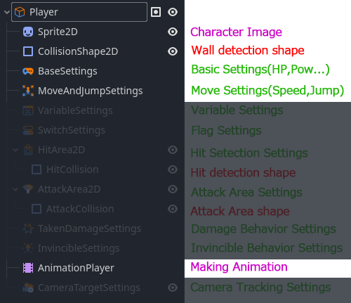
Understanding the Structure of Game Objects

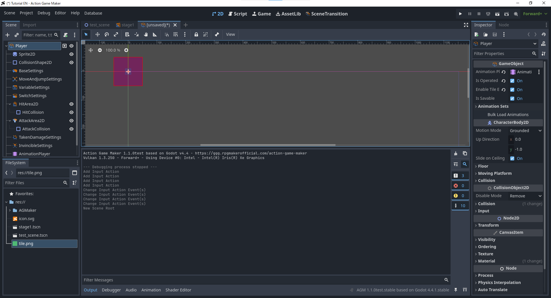
At first glance, Game Objects contain a large number of nodes, which may feel somewhat overwhelming.
However, these nodes can generally be divided into three main categories:


1. Nodes with “Settings” in their names

These nodes are used to store data that can be read and utilized by ACTION GAME MAKER’s Visual Script.

By setting values here—such as HP, attack power, movement speed, jump strength, etc.—
you can directly use these parameters within the Visual Script.


2. Nodes with “Collision” in their names

These nodes define the shapes used for collision detection. For example:
  • CollisionShape2D → Used for collisions with walls and ground
  • AttackCollision → Collision area for attack detection
  • HitCollision → Collision area used to detect when the character is hit

3. Nodes related to animations

  • AnimationPlayer → Controls character animations
  • Sprite2D → Provides the image assets used in animations

When configuring a Game Object, you will primarily work with these three types of nodes.


Visual Scripts Can Only Be Assigned to Game Objects

ACTION GAME MAKER’s Visual Scripts operate by reading data from these nodes.
Therefore, Visual Scripts can only be assigned to Game Object nodes
(in this example, the Player node).


Planning the Object’s Configuration

In this section, we only need to implement movement and jumping functionality.
Thus, we do not yet need to configure attack or damage-related content.

For now, we only require the following elements:

  • Player character image
  • Animations for movement and jumping
  • Movement speed
  • Jump strength
  • Key bindings for movement

Therefore, in this section, we will configure only the above items.

Setting the Player Character’s Sprite Image on Sprite2D

Next, we will apply the player character’s image to the Sprite2D node used to display images.
Here, we will use the sample image provided in this tutorial.


Steps

  1. Right-click the image below and save it to your computer.

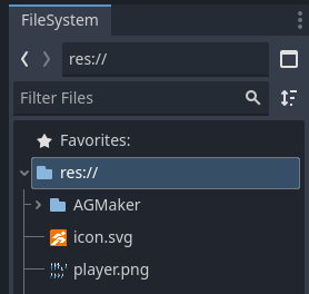
  1. Drag the downloaded image into the FileSystem to import it.

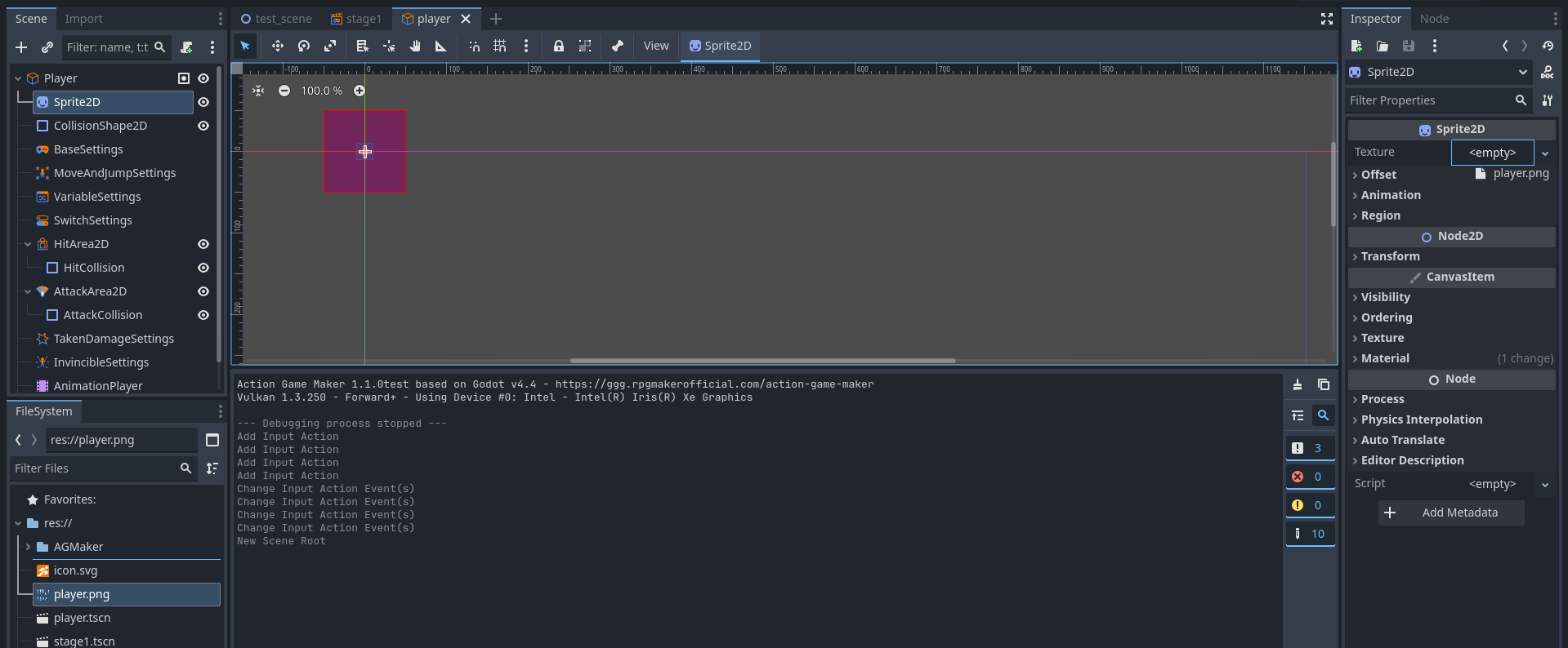
  1. Select the Sprite2D node used to display the image.

  2. In the Inspector panel on the right, locate the Texture property
    (currently displayed as \u003cempty\u003e),
    and drag the imported player.png file onto this property.

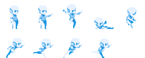
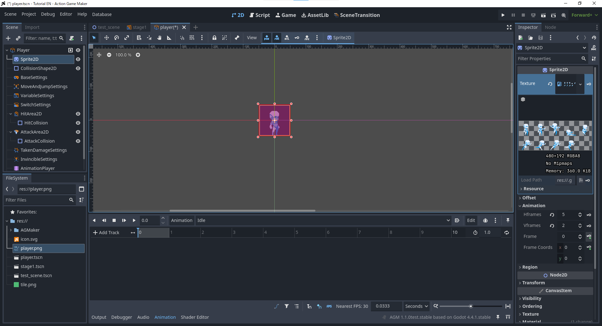
  1. The image will appear—but you’ll notice that all 9 character frames are displayed simultaneously.

  • This is because the file is a Sprite Sheet,
    meaning all animation frames are combined into a single image
    (similar to the Atlas concept mentioned earlier for tiles).

  • Therefore, we need to split the sprite sheet first
    and tell Godot which portion to display.


Splitting the Sprite Sheet

  1. In the Inspector, expand the Animation section.

  1. Set Hframes (horizontal frames) to 5,
    and Vframes (vertical frames) to 2.
  • This divides the entire image into
    5 × 2 = 10 small frames.

  1. Try clicking the up/down arrows next to the Frame property in the Inspector.

  • Each click slightly changes the displayed image.
  • This is how animations are achieved in games—
    by switching frames one by one, like a flipbook animation.

Note: Why Does the First Frame Start at 0?

You might wonder why the first frame is numbered 0 instead of 1.
In programming, lists and arrays typically start counting from 0.

Godot follows this convention, so animation frame numbering also starts from 0.

Creating Animations Using the AnimationPlayer Node

In Godot Engine / ACTION GAME MAKER, animations are created using the AnimationPlayer node.
This system employs a timeline-based approach, similar to video editing software.

On the timeline, you can create tracks for images, sounds, etc.,
and place keyframes (events) on these tracks.
As time progresses, the AnimationPlayer executes the keyframes on each track sequentially.

You can think of it as a symphony score:

  • At 1 second, the piano plays a C note.
  • At the same time, the violin plays a D note.

In this analogy:

  • Track = Instrument
  • Keyframe = Performance Instruction

Animations Required for This Tutorial

In this tutorial, we will create the following three basic animations:

  • Idle → When no input is detected
  • Jump → When the jump key is pressed
  • Move → When left/right directional input is detected

We will use the AnimationPlayer to create these animations.


Procedure

  1. In the Scene panel, select the AnimationPlayer node.

  2. A new Animation panel will appear at the bottom of the screen
    (similar to the Tile Editor from earlier).

  3. Click the Animation button and select New.

  1. A window will pop up prompting you to enter an animation name.
    First, create the Idle animation, enter the name, and click OK.

  1. The Idle animation is now created.
  • Next, we will use the previously set sprite frames to build the animation.
  1. Select the Sprite2D node.
  • Among the 9 character images, Idle uses only the top-left frame.
  • Since the top-left image is Frame 0,
    we only need the Idle animation to display Frame 0.

  1. In the Inspector, confirm that the value of Animation > Frame is 0.
  • Click the :key:+ button on its right.
image

  • This step inserts a keyframe,
    recording the current frame information into the animation being edited.
  1. A window will appear.
    Disable “Create RESET Track(s)” and click Create.


Explanation: What is a RESET Track?

RESET tracks define the initial state of the scene.
For example, you can set Idle as the default state.

However, in ACTION GAME MAKER, RESET tracks are typically not used,
so leave this option disabled.


  1. A track named Sprite2D: frame will appear on the timeline.

  • At the 0-second mark, Frame 0 of player.png is already set.
  • When the Idle animation starts playing, this image will be displayed immediately.
  • Since Idle uses only one image, the animation is now complete.
  1. Follow steps 1–8 to create the Jump animation.

  • The jump animation uses the third image in the first rowFrame 2.

  • If set correctly, Frame 2 will appear at the 0-second mark on the timeline.

  1. Finally, create the Move animation.
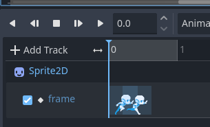
  • Unlike Idle and Jump, the Move animation uses 4 frames:

    • Images 1–4 in the second row → Frames 5, 6, 7, 8
  • To make the motion appear smooth, we will switch frames every 0.2 seconds and enable animation looping.


Creating the Move Animation

  1. As before, create a new animation named Move.

  • First, set Frame 5 at the 0-second mark.

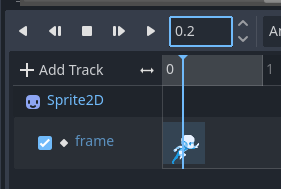
  1. Move the timeline playhead to 0.2 seconds
    (directly enter “0.2” in the time input box).

  1. Change the Sprite2D’s Frame to 6,
    then click the :key:+ button to insert a keyframe.

  • You should now see Frame 6 added at the 0.2-second mark.

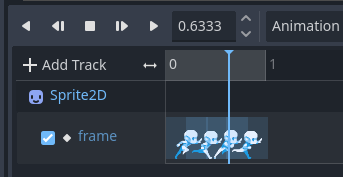
  1. Repeat the same operation:
  • At 0.4 seconds, set Frame 7.

  • At 0.6 seconds, set Frame 8.

  • Now, all 4 frames are placed on the timeline.

  1. Adjust the animation length.
  • In the top-right corner of the Animation panel, you’ll see an input box displaying 1
    (default animation length is 1 second).
  • Since we are using 4 frames, each lasting 0.2 seconds,
    change it to 0.8.

  • This ensures the animation loops smoothly without stuttering.
  1. Enable looping.
  • Next to the time input box, click the loop button (circular arrow).

  • The animation will now loop automatically.

Explanation: Difference Between Loop and Ping-Pong Loop

  • Single click: Normal loop (animation plays from start to end, then restarts).
  • Click again: Ping-Pong Loop
    (animation plays forward → backward → forward again).

image


  1. After completing all settings, click the Play button to test the animation.
  • If the animation plays smoothly, you’re done!

Troubleshooting

  • If the animation appears incorrect:

    • Select each keyframe on the timeline one by one and check its Value.
    • Confirm the sequence is 5 → 6 → 7 → 8.
    • If incorrect, manually adjust the values to fix it.
  • Also ensure:

    • The animation is set to Loop.
    • The animation length is set to 0.8 seconds.

:white_check_mark: You have now successfully created three animations for your player character:
Idle, Jump, Move.

Creating an Animation Set

In ACTION GAME MAKER, there is a system called Animation Set,
which can automatically switch to the corresponding animation based on the character’s movement direction.

By assigning animations to up to 8 directions within a single Animation Set,
you only need to select this Animation Set once.
When the character moves right, left, up, etc., the animation will automatically switch.

In this game, we only need two movement directions: right and left.
Currently, we have already created three animations: Idle, Jump, Move,
and all of them are animations facing to the right.

However, the system has the Auto Flip option enabled by default.
This means we do not need to create separate animations for the left direction—
the system will automatically mirror the right-facing animations horizontally.

Additionally, in this scenario
(where only left and right movement is required, and left-facing animations can be achieved via flipping),
we can use the Bulk Import feature
to quickly complete the Animation Set setup.


Steps

  1. In the Scene panel, select the Player node
    (i.e., the GameObject node).

image

  1. In the Inspector, click the
    Select Animation Player button.

  2. A node selection window will appear; select the AnimationPlayer node.

  1. Next, click the Bulk Load Animations button.

  1. To confirm the setup was successful, expand the Animation Set section.

  2. If done correctly, you should see the three animations—Jump, Idle, Move—in the Animation Set.


Troubleshooting

  • If animations do not appear in the Animation Set:

    • Return to Assign AnimationPlayer
      and reassign the AnimationPlayer node.

Adjusting Player Settings

Now that the animation has been created, let’s configure the player’s settings.
We need to complete the following three tasks:

  1. Set the keys used for movement
  2. Adjust the movement speed and jump power
  3. Adjust the collision shape (Collision Shape) so it matches the character’s body size

Setting Movement Keys

First, use the input actions we set up earlier to define the character’s movement keys.

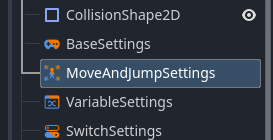
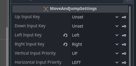
  1. In the Scene (Scene) panel, select the MoveAndJumpSettings node.

  1. In the Inspector (Inspector), make the following settings:
  • Left Move Key → Left
  • Right Move Key → Right


Adjusting Movement Speed and Jump Power

Next, let’s adjust the character’s movement speed and jump power to make them more suitable for gameplay.

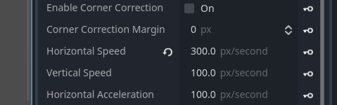
  1. Keep the MoveAndJumpSettings node selected and check the Inspector.

  2. Change the Horizontal Speed (Horizontal Speed)
    from 100 to 300.

  • This means that when holding a direction key for 1 second, the character will move 300 pixels.

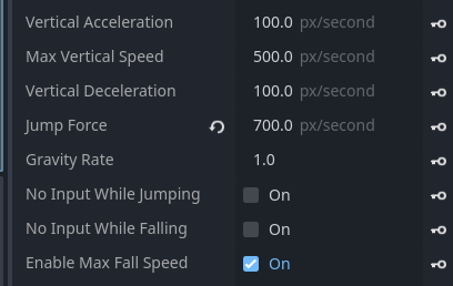
  1. Find Jump Force (Jump Force) near the bottom.
  • Change it from 500 to 700.

  • This means that when the jump key is pressed, the character will jump upward at a speed of 700 pixels per second.

Adjusting Collision Shape (Collision Shape)

The CollisionShape2D node defines the shape of the character when it collides with the ground or other objects.
Currently, this shape is too small (even smaller than the character’s head),
which causes the character’s body to “sink” into the ground.

We need to adjust it to match the character’s overall size.

  1. In the Scene (Scene) panel, select the CollisionShape2D node.
  • You will see a small blue rectangle outlined by orange dots — this is the current collision shape.

:warning: If the character is currently displaying Jump or Move animation frames,
please switch the AnimationPlayer back to Idle.

  • This makes it easier to align the collision shape with the character’s body.
  1. Click and drag the orange control points at the corners of the rectangle to adjust its size.
  • Resize the collision shape so it covers the entire body of the character.


:white_check_mark: After completing the above settings,
your character will respond correctly to input,
move and jump at appropriate speeds,
and no longer sink into the ground when colliding with it.

Using Visual Script to Make the Character Move

Now that all the preparations are complete —
Let’s use Visual Script to make the player character actually move!

First, we need to add (attach) a Visual Script to the Player.


Adding a Visual Script

  1. In the Scene (Scene) panel, select the Player node (GameObject).

  2. Click the :scroll:+ (Attach Script, Attach Script) button.
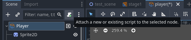
  1. A new window will pop up, asking whether to attach a VisualScript or a GDScript (standard programming script).
  • Since we selected the Player node (GameObject),
    VisualScript will be automatically selected.

  • Simply click the Create (Create) button here.
  1. The editor view will automatically switch to the Script (Script) tab.
  • You will see two boxes: State001 and AnyState.
  • This is the Visual Script workspace.


Returning to the Previous View

If you want to return to the previous editing view,
simply switch the top tab back to 2D.

As explained in the Scene Transition section,
the top tabs are used to switch what the editor currently displays.

image

Creating States

Determining Which States Are Needed

As explained in Chapter 1, the visual scripting in ACTION GAME MAKER is built by:

  1. Adding behaviors to the character’s States
  2. Connecting (switching) these states based on conditions

In this tutorial, the character only needs to walk and jump in the level, so we only need the following three states:

  • Idle
  • Move
  • Jump

By connecting and switching these three states under appropriate conditions, we can implement the basic movement behavior of the player character.

First, let’s prepare the Idle, Move, and Jump states, and assign corresponding animations and behaviors. The existing State001 can be directly used as the Idle state.


Creating the Idle State

  1. In the Script window, select State001.

  2. In the Inspector, change the Title from “State001” to Idle.

  1. In Animation to assign > Animation Select, click the blank field and select Idle.

  • This means that when the character is in the Idle state, the Idle animation sequence will play.

Creating the Move State

The Move state needs to be created as a new state.

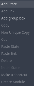
  1. Right-click in the blank area to the right of the Idle state.

  2. From the menu, select Add State (Add State).

  1. A new “State001” will appear. Rename its Title to Move.

  2. In Animation Category (Animation Category), select Move.

  • This means that when the character is in the Move state, the Move animation will play.

Creating the Jump State

The Jump state requires not only an animation but also the actual jump action.

  1. Create a new state below the Idle and Move states.

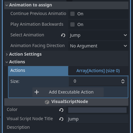
  2. As before, change the Title to Jump, and set the Animation to Jump.

  1. Expand the Action Settings (Action Settings) section.
  • Check the Jump option.

  • This means that when the character enters the Jump state, a jump action will be automatically executed.

Explanation: Why Isn’t There a “Perform Movement Action” Setting in the Move State?

Movement based on player input is already handled by the key bindings set in MoveAndJumpSettings.

This system applies to all states, so the Move state itself does not need additional action settings to achieve movement.


:white_check_mark: At this point, you have successfully created and configured the three core states:
Idle, Move, and Jump,
which are now ready to drive the character’s basic behaviors.

Connecting States with Links

Now that we’ve created three states,
Next, we’ll use Links to connect them, allowing the character to switch smoothly between states.


Thinking About State Transition Conditions

In this game, the basic logic is as follows:

  • Press Left/Right → Move
  • Press Jump → Jump
  • No input → Idle

In other words:

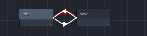
  • When pressing left/right keys → Idle → Move, and when releasing all keys → Move → Idle
  • When pressing the jump key in Idle → Idle → Jump
  • When pressing the jump key while moving → Move → Jump
  • When landing (character’s bottom touches a tile) → Jump → Idle

:backhand_index_pointing_right: So, do we need a Jump → Move link?
Actually, no.
If the movement key is still pressed when landing,
it will immediately trigger Idle → Move,
so there’s no need to jump directly from Jump to Move.


Connecting Idle and Move

  1. Right-click on the Idle state and select Add Link (Add Link).

  1. Drag a connection line from Idle to the Move state.

  • Now Idle and Move are connected.
  • Next, set the condition: switch to Move when pressing left/right keys.
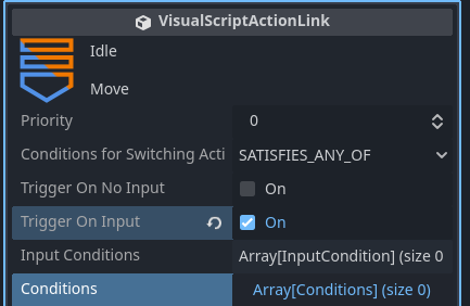
  1. Select the newly created link and check Trigger On Input in the Inspector.

  1. Expand Input Operation List (Array[InputCondition]).

  2. Click + Add Input.

  1. A \u003cempty\u003e will appear; click it and select New Input Condition.

  1. The \u003cempty\u003e will change to Input Condition; click to expand it.

  2. Set it as follows:

  • Input Target: Four Any Input Keys
  • Up Key: None
  • Down Key: None
  • Left Key: Left
  • Right Key: Right
  • Input Method: Being Pressed

  1. Now, when pressing Left or Right, the character will transition from Idle → Move.

  2. Next, create the Move → Idle link.
    Right-click on Move and select Add Link.

  3. Select the newly created link.

  1. In the Inspector, check Trigger On No input.

  • This means that when no keys are pressed, the character will return to Idle.

Placing the Player in the Level and Testing

At this point, the character should be able to move left and right on the ground.
Let’s place the Player scene into stage1.tscn and test it.

  1. Switch the editor view from Script back to 2D.

  2. Save the Player scene:
    Right-click on the player tab, and select Save Scene.

  1. Switch to the stage1.tscn tab.

image

  1. In the Scene panel, select Base (TileMapLayer).

  1. From the FileSystem, drag and drop player.tscn into the level,
    placing it on the ground.

  2. Confirm that Player is a child node of BaseLayer.

  • If the hierarchy is incorrect, adjust it in the Scene panel.
  • If the position is wrong, use Move Mode to adjust.
  1. Click Run Project (F5) in the top-right corner.

  2. If everything works correctly, the character will:

  • Walk when pressing Left/Right
  • Stop when releasing the keys

Troubleshooting Common Issues

  • Character doesn’t move
    → Check if the input keys are correctly set in MoveAndJumpSettings.

  • Character moves but animation doesn’t switch
    → Check the Idle → Move link and the animation settings in the Move state.

  • Character cannot return to Idle
    → Check the condition of the Move → Idle link.

:warning: Error message: ID is not set in CameraTargetSettings.
This occurs because CameraTargetSettings exists but hasn’t been configured.
We’ll set up camera following in Chapter 4, so you can safely ignore this message for now.


Connecting Idle, Move, and Jump

Next, let’s connect the Jump state.

  1. Switch back to the player tab and switch the editor to Script view.

image

  1. Right-click on Idle, add a link, and connect it to Jump.

  2. Select the link and enable Trigger On Input.

  1. Expand Input List → + Add Input → New Input Condition.

  1. Set it as follows:
  • Input Target: Registered key
  • Input Key: Jump
  • Condition: Moment pressed

  • This means that when the Jump key is pressed in Idle, the character will enter Jump.
  1. Next, connect Move → Jump.
  • Since the condition is the same, we can reuse the Idle → Jump link.
  1. Right-click on the Idle → Jump link and select Copy.

  1. Right-click on the Move state and select Paste Link.

  1. Drag the new link and connect it to Jump.

  2. Select the Move → Jump link and confirm the condition is set correctly (Jump key pressed).


Connecting Jump Back to Idle

  1. Right-click on the Jump state, add a link, and connect it to Idle.

  2. Since this is not input-based,
    in the Inspector, click + Add Condition.

  1. In the pop-up window, select ContactWithTile.

  2. Set the condition to
    Incoming Contact Direction → Bottom.

  • This means: only when the character’s bottom touches a tile (lands) will the transition trigger.
  1. If the link appears as follows, the setup is complete.


Test Run

Click Run Project (F5).

  • Press Z in Idle or Move → the character should jump.
  • After landing, the character should return to Idle.

Troubleshooting Common Issues

  • Cannot jump
    → Check the Idle → Jump and Move → Jump links,
    and confirm that Jump Action is enabled in the Jump state.

  • Cannot return to Idle after landing
    → Check the Jump → Idle link,
    and confirm that the “ContactWithTile (Bottom)” condition is set.


:white_check_mark: Congratulations! You’ve successfully used visual scripting to make your character smoothly idle, move, and jump!

Chapter 2 Review

In Chapter 2, we learned about the concepts of Game Scene and Game Object, and created a level and a player character.

  • In the Game Scene, we learned about the concept of Layers and how to import and place tiles.

  • In the Game Object, we learned how to import images, create animations, adjust settings, and attach visual scripts.

This workflow applies to almost all types of game development. Therefore, if you encounter difficulties in your future projects, reviewing and referring back to these steps can often help you clarify your thoughts.

At this point, you have mastered the basic operations and core concepts of ACTION GAME MAKER. In Chapter 3, we will take it a step further by adding bullet shooting and enemy characters, bringing the game closer to a finished product.

:backhand_index_pointing_right: See Chapter 3 here

1 Like