This is a tutorial course for those who want to start by experimenting with their own images.
Before taking this tutorial course, we recommend that you complete the following:
Please note that this course continues to use the project from the initial tutorial. If you have deleted it, please prepare the tutorial project again from the beginning of the tutorial.
In the file system window at the bottom left, select the folder where you want to place the image. You can also create a new folder using the right-click menu.
Drag and drop the downloaded image from your file explorer into the file system. The file test_picture.png should now be imported into the selected folder in the [File System].
Note: Not only images, but all assets must be added to the file system before they can be used.
Select any layer, then drag and drop test_picture.png from the file system to any location on the stage.
The image should now appear on the stage. When you place an image file such as a PNG, a node called [Sprite2D], which is used to handle images, is automatically generated and assigned as its texture.
When you place an image file such as a PNG, a node called [Sprite2D] for handling images is automatically generated like this. Since [Sprite2D] is just an image, it cannot be made to perform actions, but due to its low overhead, it can be used like a sticker.
Next, let’s change the pre-configured background image. Look at the scene layers on the left. You can see there are three layers: DistantView, MiddleView, and NearView. These three are the background layers. In this tutorial project, the background is divided into three layers to achieve a parallax scrolling effect.
As in STEP 1, you can see that each layer contains a [Sprite2D]. This is the background image. Select the [Sprite2D] under DistantView. At the top of the Inspector window on the right, there is a field called “Texture,” which shows the currently assigned image.
The tutorial project includes default replacement background images. Let’s try using them. Look at the file system in the bottom-left corner. Open templates > backgrounds. These are the replacement images for each layer.
Although the original background is a single small vertical image, the result is a large horizontal background. Why is that? It’s because we’re using a Godot node called [Parallax2D], which allows settings for creating parallax backgrounds. Each View node is essentially a [Parallax2D] node with a different name. Let’s take a closer look. Select the [DistantView] node.
You’ll notice several settings in the Inspector. Let me briefly explain each one.
Specifies how much the layer moves relative to the camera’s movement. Lower values make the layer move slower than the character, giving the impression of distance. For foreground elements in front of the character, set values greater than 1.
Scroll Offset
Sets the offset for the parallax effect. For now, you can safely ignore this.
Repeat Size
Specifies the repeat size. Typically, set this to match the size of the texture image used. If you replace the background with an image of a different original size, remember to adjust this setting.
Autoscroll
Makes the layer automatically move in a specified direction, allowing effects like clouds drifting left. In this image, it’s set to move 3 pixels to the right per second.
Repeat Times
The number of times the background repeats. Starting from the initial image position, it extends to the right, left, right, left, and so on.
Try changing these settings or swapping the images for Middle or Near layers, then test the game.
If you want to use your own created images, add them to the file system as in STEP 1 and apply them. In that case, be sure to adjust the Repeat Size setting accordingly.
Note
002_forest and 003_cave are materials designed to represent indoor parallax effects. If applied directly, the NearView will be misaligned. To fix this when using them, change the Y coordinate of NearView’s Node2D > Transform > Position from 360 to -180, which will align it correctly.
The node selection screen will appear. Select [TileMapLayer] and create it. It should be easier to find if you type “tile” in the search bar to filter.
*There is a similarly named [TileMap], but that is a node for an older feature, so be careful not to confuse them.
will change to TileSet. Click it again to expand and configure the settings.
Tile Size: Set this to match the size of one of your created tiles. The sample image is 24px.
After that, select Physics Layers and add a + element. Without Physics Layers, you cannot create wall collisions, and characters will not be able to stand on the tiles.
*This tutorial proceeds assuming tiles are rectangular, but you can also change the Tile Shape to quarter-view or hexagonal.
After selecting, check the panel at the bottom center and switch to the tile settings tab. This is the tab for managing tiles. From the file system, drag and drop the tiles you want to load into the panel.
Next, you can choose whether to load as an AutoTile. However, neither the sample tile nor your tile is likely in a format suitable for AutoTile. Here, press “No”. AutoTiles will be explained in the next STEP.
The tiles should now be split and loaded according to the specified size. If something is incorrect, delete them using the trash button and reload. Next, let’s create wall collisions for the tiles. After switching the tab to Select, drag on the right-side screen to select all tiles at once.
The tile settings screen will open. Open Physics > Physics Layer 0. If it’s missing, check step 4 to ensure you didn’t forget to create the physics layer.
Select the Add Point tool and click the four corners to add vertices for the wall collision. Select the four corners, then click the first vertex again to close the polygon. The red wall collision is now created.
*When adding the top-left vertex, be careful not to accidentally change the zoom level.
*If a vertex is misaligned, you can move it using the blue arrow tool. You can also delete vertices using the red X tool.
*If you are creating a tile where the wall collision is not square, select only that tile and edit the vertices to create a correctly shaped wall collision.
Switch the panel to TileMap, and you can now place tiles. Select your favorite tile and place it. Since wall collisions are also set, you should be able to stand on them during test play.
*If created as specified, this tile will appear in the foreground of the BaseLayer. In Godot, nodes lower in the Scene view are rendered in front. If you want to change this, try reordering by dragging and dropping the TileMapLayer.
Well, you have now set up your original tiles, but configuring them one by one is a bit inconvenient. In the next STEP, let’s try AutoTiles.
STEP 4: Auto-Tile
The Auto-Tile feature in ACTION GAME MAKER utilizes Godot’s Terrain function. https://docs.godotengine.org/en/4.x/tutorials/2d/using_tilesets.html#creating-terrain-sets-autotiling
With this function, you can freely create Auto-Tiles for ease of use. However, ACTION GAME MAKER also provides a feature to automatically import Auto-Tiles when images are created in a predefined format.
Let’s try out this feature now.
First, download the following test tile image and import it into your file system.
Following the same steps as in STEP 3, select the TileMapLayer you wish to import. This sample has a size of 24×24. If you used a different tile size in STEP 3, please specify the existing [Base] layer or others accordingly.
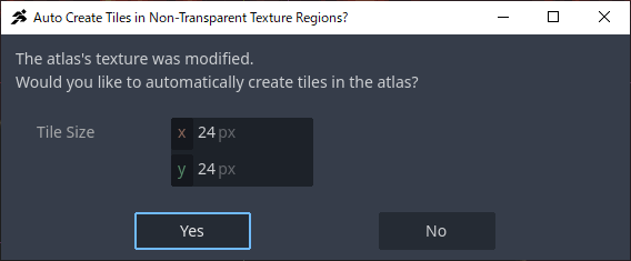
Open the TileSet panel located at the bottom center and drag & drop test_autotile.png from the file system. As before, the tile splitting window will appear; select “Yes.”
In the subsequent window asking whether to import in Auto-Tile format, unlike before, select “Yes.” This will automatically configure “Wall Collision Settings” and “Terrain Settings,” making the tile ready for use as an Auto-Tile.
Switch the bottom panel from TileSet to TileMap and select Terrains. The tile you just created should now be set as auto_tile_00 under Terrain_Set X.
*If it is not displayed, try selecting another node first and then reselecting it; this may resolve the issue.
Select Terrains and try placing the Auto-Tile. You will notice that the tiles automatically change based on the shapes of adjacent tiles. This sample tile visualizes connection relationships to make the Auto-Tile placement logic easier to understand.
If you create tiles in the same format as this Auto-Tile, they can be imported as Auto-Tiles even if the tile size is not 24×24. To facilitate creating your own Auto-Tiles, we have prepared an image with non-collision areas made transparent. Use this as a reference when creating your own Auto-Tiles.