Tutorial: "ACTION GAME MAKER from Scratch" Chapter 4

Chapter 4: Establishing It as a “Game”

In the previous chapter, we completed the basic mechanics of shooting bullets to defeat enemies.

This time, we will explain how to make it “actually playable as a game.”

Considering What Is Missing for a Game

In the current version, we have implemented player movement and enemies, but there are several missing elements.

First, the stage seems too narrow, so it needs to be expanded.

Additionally, while the player has a damage reaction, they are in an “invincible” state. Since the current HP is unknown, we need to make it visible.

Finally, there is no “objective” for the game. Ideally, we would include a boss battle, but for simplicity this time, let’s set the goal as “clear the game by defeating 5 enemies.”

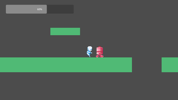
Completion Concept

Let’s Extend Stage1

First, let’s expand the stage by painting tiles. As the stage becomes larger, it will extend beyond the camera’s view, so we’ll need to make the camera follow the player.

Let’s Paint and Expand the Tiles

Tiles are created using the Base (TileMapLayer) node. Let’s use this node to expand the stage.

  1. Switch to the stage1 scene tab.

  2. In the Scene window, select the Base (TileMapLayer) node.

  3. In the “Tile Placement” window at the bottom, select a tile.

  1. Try freely placing tiles in the space on the right. To make it easy to jump over, keep the height of aerial platforms and walls within 4 tiles, and make the width of pits around 4 tiles as well.

Once you’ve created a certain amount, proceed to the next step.

Let’s make the camera follow the player.

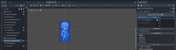
Camera following is handled by a system called “Target ID”. Remember when we created the “CameraTargetSettings” node during player creation? In its properties, you can set a “Target ID”.

The camera node “ZoomCamera2D” in ACTION GAME MAKER also allows you to set a “Target ID” and is designed to follow game objects that share the same “Target ID”.

Now, let’s set the “Target ID” for both “ZoomCamera2D” and “CameraTargetSettings”.

Set the Target ID on the IntialCamera (ZoomCamera2D) node.

  1. Select the IntialCamera (ZoomCamera2D) node in the Stage1 scene tab.

  2. Expand the Target ID Array… in the Inspector.

  3. Click the “+ Add Element” button.

  1. The string “” will appear; delete it and enter “player”.

Add the Target ID to the “CameraTargetSettings” node of the Player.

  1. Switch the scene tab to “player”.

  2. Select the “CameraTargetSettings” node.

  3. Enter “player” in the “Target ID” field of the Inspector.

Test play the expanded stage.

Try test playing to see if it works correctly and if you can reach the right edge of the stage.

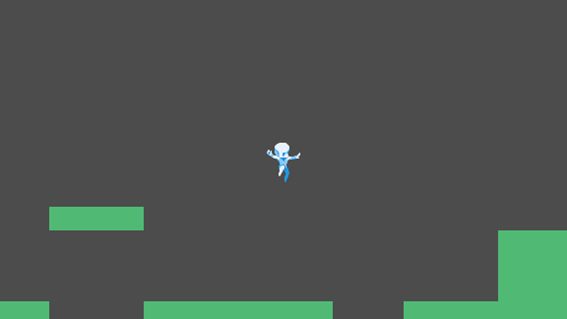
If everything is working properly, the camera should follow the player.

Checklist

If it doesn’t follow: Check the InitialCamera in stage1 and the CameraTargetSettings of the player.

If you can’t reach the right edge of the stage: Adjust the size of the pitfall or the height of the walls in Base (TileMapLayer).

Add “Defeated” State to the Player: Creating Particles

Just like enemies, the player should be defeated when their HP reaches 0. Since there doesn’t seem to be a suitable frame for the “defeated” state, let’s add a visual effect using “particles.”

What are “Particles”?

In Japanese, “particles” translates to “particles.” They are used to create visual effects by scattering many small images. You can think of it like confetti. You can freely adjust the appearance and movement of the “confetti,” such as how the paper looks and how it flies.

In Godot Engine, this can be achieved using nodes called “GPUParticle2D” and “CPUParticle2D.” In ACTION GAME MAKER, it is handled using a node called “ParticleObject.”

Furthermore, “ParticleObject” supports over 20 particle templates.

Let’s Create a Particle Object

The creation process is exactly the same as for game objects.

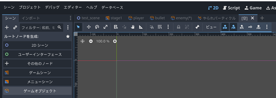
  1. Create a new Scene tab.
  2. Create a root node: Select “Game Object.”
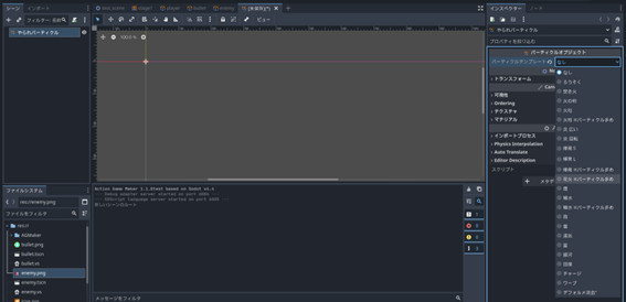
  3. Set the object name to “Defeated Particle,” select the “Particle” template, and click “Create.”
  4. Select the created “Defeated Particle” node in the Scene window.
  5. In the Inspector, change the Particle Template from “None” to “Fireworks (High Particle Count).”
  6. A “GPUParticles2D” node will be automatically added.
  7. Check the “Emitting” property in the GPUParticles2D Inspector. This property controls the emission of particles.
  8. Particles should now be emitted in the Scene view, creating a fireworks effect. Right-click the Unsaved tab and save the file as “defeated_particle.tscn.”

Add a “Defeated” State to the Player’s Visual Script

Considering the “Defeated” State

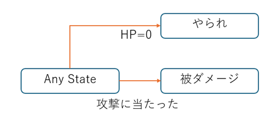
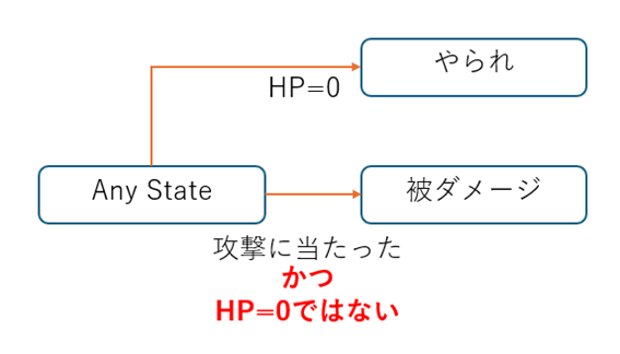
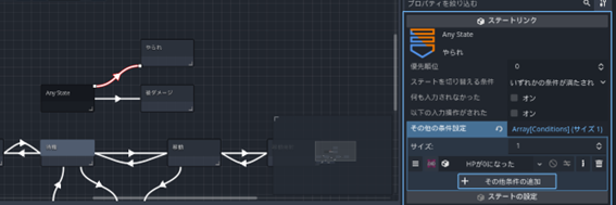
It seems best to configure the player so that when HP reaches 0, they become immobile and emit “Defeated Particles.” While it might seem logical to link from AnyState, there is one issue. As shown in the diagram below, the transition to the “Take Damage” state occurs upon being attacked regardless of the current state.

Since reaching 0 HP means the enemy has already attacked, there is a risk that being attacked again while in the “Defeated” state could trigger a transition back to “Take Damage.”

Therefore, let’s prevent this by adding a condition to the link to “Take Damage” that checks if “HP is not 0,” as shown below.

Creating the “Defeated” State

Since there isn’t a suitable animation available, we will reuse the “Take Damage” animation. However, using it exactly as-is makes it impossible to distinguish the defeated state. Therefore, let’s use the “Filter” function to change the object’s appearance.

  1. Open the Player scene.
  2. Switch the editor view from 2D to Script.
  3. In the “Take Damage” information space, click “Add State.”
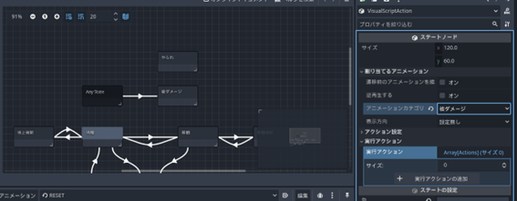
  4. Change the state name to “Defeated.”
  5. Set the animation category name to “Take Damage.”

  1. Expand “Action Settings.”
  2. Turn on the property “Disable Movement Input During Action.”

  1. Select the “+ Add Execute Action” button.
  2. Select the “Show Particles” action.
  3. Click the :page_with_curl: icon next to the Particle Object path and select the “defeated_particle.tscn” file you created earlier.

  1. Select the “Add” button.
  2. Select the “+ Add Execute Action” button again.
  3. Select “Set Filter.”
  4. Change the Filter Type to “Transparent” and set the “Time to Completion (seconds)” to 3.0. This will make the object gradually become transparent over 3 seconds.

  1. Press the “Add” button. If the settings look like the image below, the state creation is complete.

Creating a Link from AnyState to the “Defeated” State

  1. Right-click on AnyState, select “Add Link,” and connect it to “Defeated.”
  2. Click the “+ Add Other Condition” button.

  1. Select the “HP Reached 0” condition and click “Add.”

Adding Transition Conditions to “Take Damage”

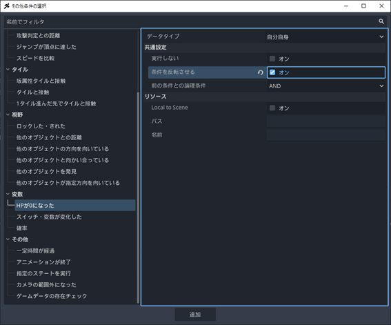
Finally, add the transition conditions to “Take Damage.” By enabling “Invert Condition” in the common settings, you can reverse the logic. In other words, the “HP Reached 0” condition can be inverted to mean “HP is not 0.”

  1. Select the link from AnyState to “Take Damage.”
  2. Select the “Add Other Condition” button.

  1. Select the condition “HP Reached 0.”
  2. Turn on “Invert Condition” and add it.

  1. If the “Other Conditions” field looks like the image below, it is correct. When the “Invert” option is active, the “≠” icon turns white, so verify that the inversion is working correctly.

Test Play the “Defeated” State

Let’s test play. Currently, the initial HP is set to 1, so taking one hit from an enemy should trigger the “Defeated” state.

If implemented correctly, hitting an enemy will display particles, and the player will gradually fade away. Note that after being defeated, you can reset the game by pressing the “F5” key.

Checklist for Troubleshooting

Firework particles do not appear: Review the contents of the “Defeated Particles” object and the “Show Particles” action.

Does not become transparent: Review the contents of “Set Filter.”

“Take Damage” reaction appears: Review the link conditions.

Let’s Create an “HP Bar”

Now, since being knocked out in one hit is too harsh, let’s increase the HP value. This means we need to know how much HP is currently remaining, so let’s create an HP bar.

In ACTION GAME MAKER, you can display gauges using nodes called SimpleGauge and ImageGauge. For this tutorial, let’s use SimpleGauge.

However, since the camera moves, placing the HP bar on the same layer as the player would cause it to be left behind. For elements that need to be always visible, such as an HP bar, use the “UI” layer.

About the “UI” Layer

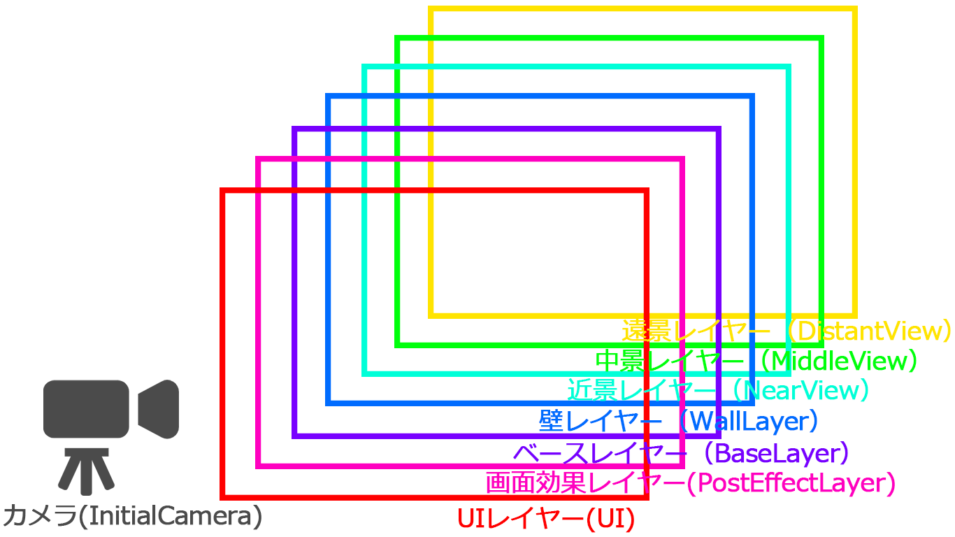
Do you remember the previous explanation? The layers in ACTION GAME MAKER are structured as follows. The UI layer and the Screen Effect layer are “special layers unaffected by the camera.” This means that nodes placed in these layers are always visible, making them perfect for placing an HP bar. Since the Screen Effect layer is a special layer used for “Screen Effect” actions, let’s place our HP bar in the UI layer.

Set the Player’s “HP” and “Max HP” values to 10.

  1. Select the BaseSettings node of the player.
  2. In the Inspector, change the values of “HP” and “Max HP” from 1 to 10.

Add and Configure the “SimpleGauge” Node.

  1. Switch the Scene tab to stage1 and return the editor view from Script to 2D.
  2. Select the UI node.
    Image151
  3. Click the + (Add Child Node) button in the top-left corner of the Scene window.
  4. Select SimpleGauge and click “Create”.
  5. First, adjust the position. It should currently look squashed as shown below.
  6. Drag the orange points to expand the gauge to a size similar to the image.
  7. The display range of the UI layer is the area enclosed by the thin blue lines shown below. Move the gauge to the upper-left area within this range.
  8. Next, configure this gauge to display the player’s HP. In the Inspector window, set the Variable Type to “Specific Object”.
  9. Click the :page_with_curl: icon that appears for “Specify Path of Target Object”.
  10. Select player.tscn and click “Open”.
  11. The “Variable Name” field should default to “hp”, so no change is needed. This field is used to specify the variable to be used as the “Current Value”.
  12. Next, check the box for “Use Variable as Maximum Value”.
  13. Repeat steps 9~10 and specify player.tscn again.
  14. The variable to be used as the maximum value should be “object_id”. Click it and change it to “max_hp”. This sets the maximum HP as the maximum value for the gauge.

Test the “HP Bar”

Press the Test Play button to test it. If configured correctly, taking damage from an enemy should trigger a damage reaction and cause the HP bar to decrease.

Checklist for when things don’t work

Gauge is not visible: Check if SimpleGauge is correctly set as a child of the UI layer and placed within the area enclosed by the blue lines.

HP is low from the start: Check if the “HP” value in the Player’s BaseSettings has been changed to 10.

HP drops to 0 in one hit despite being at maximum: Check if the “Max HP” value in BaseSettings is set to 10 and if the “Use Variable as Maximum Value” in SimpleGauge is correctly specified.

Set Up “Fall Death”

You may have noticed during test play that currently, if you fall into a pit, you keep falling indefinitely. Let’s set it up so that falling into a pit results in death.

It seems we should restrict the range in which the camera can move to prevent it from chasing indefinitely, and configure it so that going outside the camera’s range results in “death.”

Restrict the Movement Range of InitialCamera (ZoomCamera2D)

  1. Select the InitialCamera node.

  2. Expand the “Limits” section in the Inspector.

  1. Change the “Bottom” value of the limits from 10000000 to 500. Now, the camera can only move down 500 pixels from the red line.

  1. Try test play. If configured correctly, the camera should follow left, right, and upward, but should stop following once it reaches a certain position downward.

Checklist if it doesn’t work

If nothing appears on the camera: The tiles may be misaligned from the origin (where the red and green lines intersect). Try changing the camera’s limit values to 1000, 2000, etc., to find the appropriate value.

Add “Fall Death” to the Player’s Visual Script

Since the “Death” state itself already exists, let’s add a new condition to the link: “Outside the camera’s range.”

  1. Switch the Scene tab to Player and the Editor screen to Script.

  2. Select the link from AnyState to Death.

  3. Click “+ Add Other Condition.”

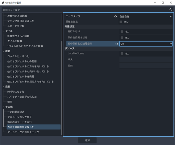
  1. Select the condition “Outside the camera’s range.”

  2. Change the data type from “Unset” to “Self.”

  3. Change the “Logical condition with previous condition” to OR and add it.

  1. It should look like the following. Confirm that “Outside the camera’s range” is connected with “OR.”

Test “Fall Death”

Perform a test play and fall down. If you fall into a pit and see the firework particles when going out of range, it’s a success.

Checklist if it doesn’t work

Check if the conditions on the AnyState → Death link are correctly set to “HP is 0”, “OR”, and “Outside the camera’s range.”

Let’s Consider “Clear by Defeating 5 Enemies”: Handling Variables

We need a way to count the number “5”. The goal is for this number to decrease each time an enemy is defeated, and when it reaches 0, a clear sequence is triggered. In game development, we handle this using “variables.”

What is a “Variable”?

A “variable” is like a container for storing values. The Health Points (HP) we discussed earlier are actually variables; when “hit by an enemy attack,” the value in the HP container decreases by one.

There are two main ways to set up variables in ACTION GAME MAKER: one is using the VariableSettings node of an object, and the other is using “Project Variables” in the database. The “Health” we discussed earlier falls under the former category.

Difference Between “VariableSettings Variables (Object Variables)” and “Project Variables”

The difference is that “Object Variables” are dedicated containers belonging to specific objects, while “Project Variables” are shared containers accessible by anyone, anywhere.

The major distinction is that “Object Variables” are attached to objects and disappear when the object is deleted, whereas “Project Variables” remain usable as long as you are within the same project. Data tied to specific objects, such as “Health” or “Attack Power,” should use Object Variables. Data you want to save even when switching save files, like “High Score,” or data you want to retain across stages, such as “Coin Count” or “Remaining Lives,” should use Project Variables.

So, which variable should we use for “Remaining Enemy Count”?

Technically, either would work, but since multiple objects might need to manipulate this value, let’s create it as a “Project Variable” this time.

When an enemy enters the “Disappear” state, decrement the “Remaining Enemy Count” by 1. When the “Remaining Enemy Count” reaches “0,” trigger the clear sequence. This approach seems feasible.

How to Implement the Clear Sequence

It is best to create a dedicated game object to check the remaining enemy count and place it on the UI layer that is always visible. By displaying the current kill count on this object, similar to an HP bar, we can also solve the problem of players not knowing how many more enemies they need to defeat. Let’s proceed with the following steps: create a “Project Variable” named “Remaining Enemy Count,” add an action to the “Disappear” state of the “enemy” object to increment the kill count, and finally, place the clear sequence object.

Add “Remaining Enemies” to “Project Variables”

“Project Variables” are located in the database. Let’s add it right away.

  1. Click the “Database” button from the menu in the top-left corner of the screen.

Image168

  1. A new window called the “Data Management Window” will open.

  2. The “User Database” tab will open, so switch to the “Project Variables” tab.

  1. Click the “+” button in the top-left corner of the window.

  1. A new row named “variables1” will appear at the bottom of the window. Rename it to “Remaining Enemies”.

  2. Since the number of enemies is 5, set the “Value” to 5.0.

  1. Click OK to close the window, and you’re done.
1 Like

Add an action to the “Disappearance” state of the “enemy” object.

In ACTION GAME MAKER, the “Change Property” action is used to manipulate variables. Since you can modify variables using arithmetic operations (add, subtract, multiply, divide), you can achieve this by setting “Remaining Enemies”, “Subtract”, and “1”.

  1. Open the “enemy” scene tab and switch the editor view to “Script”.

  2. Select the “Disappearance” state and click “+ Add Execution Action”.

  1. Select the “Change Property” action.

  2. Configure the settings as follows:

Target Object Type: Project Database
Database Type: Project Variables
Record Name: Remaining Enemies
Calculation Formula: -=
Constant Value: 1

Be careful as there are five configuration items.

With this setup, executing this action will subtract 1 from the project variable “Remaining Enemies”.

  1. Finally, reorder the execution actions. Currently, the display order should look like the image below. However, since execution actions run from top to bottom, leaving them as is will cause the object to “Disappear” before the “Change Property” action is executed, rendering the change ineffective.

Click and drag the three-line icon next to the “Change Property” action to reorder them, ensuring “Change Property” comes first.

Note: Why use “-=” instead of just “-”?

This notation is common in programming. The “-=” is a shorthand for a specific expression.

It omits the “-” and “=” from the expression: “Previous Remaining Enemies Value” - “1” = “New Remaining Enemies Value”.

Without the “=”, there would be no specification on which variable to store the result of subtracting “1” from the “Previous Remaining Enemies Value”.

Let’s create a UI object for “Remaining Enemies Management”

We will create a UI object to manage the number of remaining enemies.

This object will display the “current value of remaining enemies” and trigger a clear effect when the value reaches 0. For clarity, display the variable “Remaining Enemies” via an action next to the “Enemy Icon” shown using Sprite2D. The enemy sprite image can be used directly as the enemy icon image.

  1. Switch the editor view to “2D”.

  2. Open a new scene tab and create a root node: specify “Game Object”.

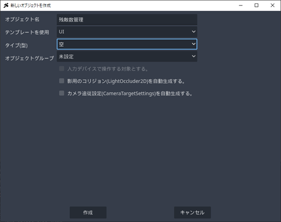
  3. Set the object name to “Remaining Enemies Management”, set “Use Template” to “UI”, set “Type” to “Empty”, and then press the Create button.

  1. Once created, save it.

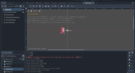
  1. Drag and drop “enemy.png”, which is used for the enemy sprite image, from the “File System” to the space to the left of the origin (the point where the red and green lines intersect) in the editor view.

  2. A Sprite2D named “Enemy” will be added automatically. In Godot Engine, placing an image file directly onto the editor view automatically generates a Sprite2D node and sets it as a texture.

Setting Up the Visual Script for “Remaining Enemy Count” Management (Variable Display Edition)

First, let’s consider only the variable display. It seems sufficient to have just the “Count” state to display the “Remaining Enemy Count” variable.

To display variables, use the “Display Text” action.

Creating the “Count” State

  1. Attach a script using the “:page_with_curl:+” button in the Scene window.

  2. Create a file named RemainingEnemyCount.vs.

  1. Rename the default state 001 to “Count”.

  2. Select the execution action “Display Text”.

Configure the basic settings as follows:

  • Text Type: Variable
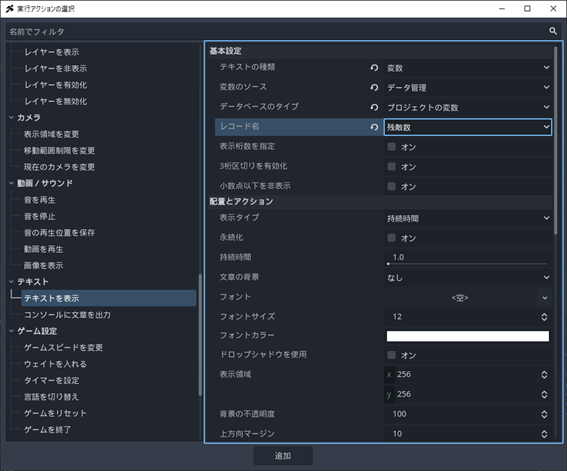
  • Variable Source: Data Management
  • Database Type: Project Variables
  • Record Name: Remaining Enemy Count

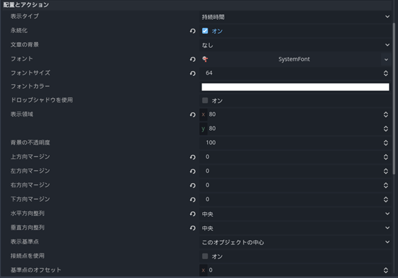
  1. Configure the “Placement and Action” settings as follows:
  • Persistence: On
  • Font: New SystemFont
  • Font Size: 64
  • Display Area: x=80, y=80
  • Margins (Top, Left, Right, Bottom): All 0
  • Horizontal Alignment: Center
  • Vertical Alignment: Center

Note: Regarding the placement of the “Display Text” action

This action creates a text box of a specified size centered on a reference point, and displays text (variable) inside it for a specified duration. The display reference point “Center of This Object” refers to the origin (the point where the red and green lines intersect).

In this case, a text box of 80x80 pixels centered on the origin is created, the variable is displayed in the center, and the display duration is set to persistent.

Testing the “Count” State

Let’s place it in the scene and test whether the count is displayed correctly. Since we want it to always be visible, the placement layer should be the UI layer.
  1. Switch to the stage1 scene tab and change the editor view to 2D.
  2. Select the SimplaGauge node located in the UI (CanvasLayer).

  3. In the file system, select RemainingEnemyCount.tscn and drag and drop it near the top-right corner of the UI layer’s display area (blue frame).

  1. Run a test play and confirm that the remaining enemy count “5” is displayed correctly, and that the number changes to “4” when an enemy is defeated.

Checklist for Troubleshooting

  • Neither the icon nor the number is displayed: Ensure it is correctly placed in the UI layer and within the blue frame area.
  • The icon is displayed but the number is not: Check whether the icon is correctly positioned near the origin in the RemainingEnemyCount object, and verify the content of the “Display Text” action in the “Count” state.
  • The number does not change even after defeating an enemy: Confirm that the processing order in the disappearance state of the enemy object is correctly set to “Change Property” followed by “Self-Destruct”.

Let’s Create a Clear Effect

Next is the clear effect. Let’s use the “Display Text” action for this as well.

Displaying “STAGE CLEAR” large in the center of the screen should make it look like a clear screen.

The transition condition should be set so that it triggers when the variable “Remaining Enemies” becomes 0.

  1. Change the Scene tab to “Remaining Enemies Management” and switch the editor view to Script.

  2. Add a new state near the Count State.

  3. Rename the title to “Stage Clear”.

  4. Click “+ Add Execution Action”.

  1. Select the “Display Text” action.

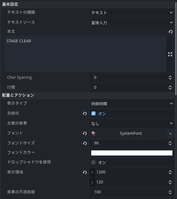
  2. Configure the settings as follows. (Please note there are many settings.)

Text: “STAGE CLEAR”

Persistence: On

Font: New SystemFont

Font Size: 96

Display Area: x=1200, y=120

Horizontal Alignment: Center

Vertical Alignment: Center

Reference Point: Based on Scene

Anchor: Center

What does “Reference Point: Based on Scene” mean?

Instead of using the position of this game object, it uses the entire game scene, i.e., the area displayed by the camera, as the reference. In this case, the text “STAGE CLEAR” will be centered within a region of width 1200 and height 120 starting from the center of the scene.

  1. Right-click the Count State, select “Add Link”, and connect it to the “Stage Clear” state.

  2. Click the “+ Add Other Condition” button.

  1. Select the “Switch/Variable Changed” condition.

  2. Set the following:

    • Variable Type: Variable
    • Data Type: Project Variable
    • Database Record Name: Remaining Enemies
    • Variable Operator: =

With this setup, the transition will occur when the “Remaining Enemies” variable becomes 0.

Let’s Test the Clear Effect

First, since there aren’t enough enemies, increase the count to 5, then test whether the clear effect appears correctly.

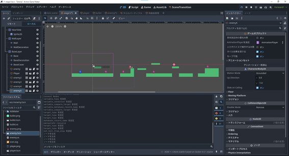
  1. Change the Scene tab to “stage1” and switch the editor view to 2D.

  2. Select the child nodes of BaseLayer, such as the enemy node and player node.

  3. Drag and drop enemy.tscn from the file system onto the stage to place it.

  1. Repeat steps 1–3 until you have placed up to 5 enemies.

  2. Try playing the test.

If configured correctly, the text “STAGE CLEAR” should appear when all enemies are defeated.

Checklist if it doesn’t work

  • The 5 enemies you placed are missing: They might have fallen and moved off-screen. Check if they are correctly placed on the floor and whether the “Prevent Falling from Template Steps” option is enabled.

  • Nothing happens even when the count reaches 0: Verify that the content of the Stage Clear state and the transition conditions are correct.

Chapter 4 Review

In this chapter, by learning about “camera following mechanics,” “particles,” “UI,” and “variables,” the game has become functional.

However, as it stands, the presentation is still quite plain, and there is no sound.

In the next chapter, Chapter 5, we will work on “sound settings” and “background settings” to enhance the game’s completeness and try exporting it so that anyone can play.