このチュートリアルコースは、すぐに独自の画像で実験を始めたい方のために設計されています!
このコースを始める前に、以下の入門編を完了することをお勧めします:
![]() Tutorial: Beginner Course
Tutorial: Beginner Course
このコースでは、初期チュートリアルで使用されたのと同じプロジェクトを継続して使用します。
そのプロジェクトを削除してしまった場合は、先に進む前に初期チュートリアルに戻り、チュートリアルプロジェクトを再作成してください。
このチュートリアルコースは、すぐに独自の画像で実験を始めたい方のために設計されています!
このコースを始める前に、以下の入門編を完了することをお勧めします:
![]() Tutorial: Beginner Course
Tutorial: Beginner Course
このコースでは、初期チュートリアルで使用されたのと同じプロジェクトを継続して使用します。
そのプロジェクトを削除してしまった場合は、先に進む前に初期チュートリアルに戻り、チュートリアルプロジェクトを再作成してください。
![]()
ファイルシステム内で右クリックすることで、新しいフォルダを作成することもできます。
選択したフォルダに test_picture.png が表示されているはずです。

注意:これは画像だけでなく、すべての種類のアセットに適用されます。プロジェクトで使用するには、まずファイルシステムにインポートする必要があります。
test_picture.png をステージにドラッグ&ドロップします。PNG などの画像ファイルを配置すると、Sprite2D というノードが自動的に作成され、そのテクスチャとして画像が割り当てられます。
Sprite2D について:PNG などの画像ファイルを配置すると、Sprite2D ノードが自動的に生成されます。
Sprite2D はシンプルな画像ノードです。アクションを実行することはできませんが、軽量であり、シールや背景の装飾などに最適です。
左側の [Scene] パネルには、DistantView、MiddleView、NearView の 3 つのレイヤーが表示されています。
これら 3 つのレイヤーが背景を構成しています。
このチュートリアルプロジェクトでは、パララックススクロール効果を作成するために、背景を 3 つのレイヤーに分割しています。
Sprite2D ノードが含まれています。このノードが背景画像を保持しています。
DistantView 下の Sprite2D を選択してください。
右側の [Inspector] ウィンドウには、Texture というプロパティが表示されます。これが現在割り当てられている画像です。
左下の [File System] ウィンドウで、templates > backgrounds フォルダを開きます。
これらは各レイヤー用の事前作成された背景画像です。
03_DistantView フォルダを開き、B_004_snow_03.png を先ほどの Texture フィールドにドラッグアンドドロップします。それは、パララックス背景効果を作成するために、Parallax2D という特別な Godot ノードを使用しているためです。
各「View」ノード(例:DistantView)は、本質的に名前が変更された Parallax2D ノードです。
中身を見てみましょう。DistantView ノードを選択してください。
それぞれの簡単な説明を以下に示します:
| プロパティ | 説明 |
|---|---|
| Scroll Scale | カメラの動きに応じてレイヤーがどの程度移動するかを制御します。値が低いほど移動が遅くなり、レイヤーが遠くにあるように見えます。前景要素には 1 以上の値を使用してください。 |
| Scroll Offset | パララックス効果にオフセットを追加します。今は無視してください。 |
| Repeat Size | 画像がどのサイズで繰り返されるかを指定します。通常はテクスチャ画像と同じサイズに設定します。カスタム画像に置き換える場合は、必ずこれを更新してください。 |
| Autoscroll | レイヤーを指定された方向に自動的にスクロールします(流れる雲などに便利です)。この例では、1 秒間に 3px 右にスクロールします。 |
| Repeat Times | 背景が何回繰り返されるかを設定します。右、左、右、左の順に中心から外側へ拡大します。 |
これらの設定を調整したり、Middle および Near レイヤーの画像を置き換えたりしてみてください。その後、プロジェクトをテスト再生して効果を確かめてください。
独自の画像を使用する場合は、STEP 1 の手順に従ってインポートしてください。Repeat Size を画像に合わせて更新することを忘れないでください。
背景の 002_forest と 003_cave は、屋内のパララックスシーン用に設計されています。
これらを直接使用すると、NearView が位置がずれて表示される可能性があります。
これを修正するには、NearView > Node2D > Transform > Position の Y 位置 を 360 から -180 に変更してください。
これで新しいタイルレイヤーを作成し、独自のタイルグラフィックを読み込んでみましょう。
タイル素材が用意されていない場合は、このサンプルタイルをお使いください:
[Scene] ウィンドウで BaseLayer を選択し、+ ボタンをクリックします。
TileMapLayer を選択します。検索バーに「tile」と入力して結果を絞り込みます。
TileMapを選択しないように注意してください。
TileSet を割り当てます。[Inspector] ウィンドウで TileSet の横にあるドロップダウンをクリックし、New TileSet を選択します。
これを行わないと、プレイヤーはタイルの上に立つことができません。
このチュートリアルでは正方形のタイルを前提としていますが、必要に応じてタイルの形状をアイソメトリックまたは六角形に変更できます。
このタブではタイルを管理できます。
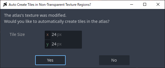
[File System] からタイル画像をこのパネルへドラッグ&ドロップします。
タイルサイズが正しいことを確認し、「Yes」をクリックします。
サンプルおよびおそらくあなたのタイルもオートタイリング用に設計されていないため、No を選択してください。
オートタイルについては次のステップで説明します。
何か問題があった場合は、ゴミ箱アイコンを使用して削除し、再度お試しください。
次に、衝突領域(壁検出)を定義しましょう。
Select タブに切り替え、すべてのタイルをドラッグして選択します。
Physics > Physics Layer 0 に移動します。
表示されない場合は、手順 4 で物理レイヤーを追加したか確認してください。
形状を閉じるために最後の点を再度クリックします。赤い衝突の輪郭線が表示されるはずです。
ヒント:
- 左上隅をクリックする際は注意してください。ズームインすると誤クリックを防げます。
- 青い矢印ツールで点を移動したり、赤い「X」ツールで点を削除したりできます。
- 一部のタイルが完全な正方形でない場合は、個別に選択し、点 accordingly に調整してください。
タイルを選択してクリックし、配置します。
衝突が定義されているため、テストプレイではプレイヤーがその上を歩けるはずです。
Godot では、Scene ツリーで下にあるノードほど手前に描画されます。
描画順序を変更したい場合は、Scene ウィンドウでTileMapLayerを上下にドラッグしてください。
独自のカスタムタイルの作成と設定が成功しました!
ただし、各タイルを手動で設定するのは時間がかかる場合があります。
次のステップでは、作業を効率化するための Auto Tiles について解説します。
ACTION GAME MAKER は、オートタイル機能に Godot の Terrain システム を採用しています。
詳細はこちら:
![]() https://docs.godotengine.org/en/4.x/tutorials/2d/using_tilesets.html#creating-terrain-sets-autotiling
https://docs.godotengine.org/en/4.x/tutorials/2d/using_tilesets.html#creating-terrain-sets-autotiling
この機能により、柔軟なオートタイルの作成が可能ですが、ACTION GAME MAKER では、タイル画像を特定の形式で用意するだけで、オートタイルとして自動的に読み込まれます。手動での設定は不要です。
それでは、この機能を試してみましょう。

TileMapLayer を選択します。サンプルのタイルサイズは 24×24 です。
ステップ 3 で異なるサイズを使用した場合は、既存のレイヤー(例:[Base])を使用することをお勧めします。
test_autotile.png をドラッグしてパネルに配置します。前回と同様にスライス設定ウィンドウが表示されますので、Yes をクリックしてください。
これにより、以下の設定が自動的に構成されます。
新しく作成されたタイルが、Terrain_Set X → auto_tile_00 のような項目の下に表示されているはずです。
タイルの形状が、周囲のタイルに基づいて自動的に変化することに気づくでしょう。
このサンプルタイルは、オートタイルリングの仕組みを理解しやすくするために、接続ルールを明確に可視化しています。
タイルサイズに関係なく機能します。
お手伝いとして、独自のデザインを行う際のガイドとして使用できる、透過処理済みの オートタイルテンプレート を用意しました。