Let’s Set Up “Tiles”
Now, let’s begin creating the platforms.
We need a ground and platforms in the air to jump onto. While there are various nodes used to create platforms, since we will be creating platforms of various shapes over a wide area, it is necessary to use nodes suitable for this purpose.
This time, let’s create them in “Tile” format. As the name suggests, “Tile” is a format where platforms are built by laying down small tile-like images.
Load Tile Images into the File System
First, let’s use the following image for the tiles.
Right-click the image to download it.

As explained in Chapter 1, in Godot Engine, you must first place assets into a “File System” warehouse to handle them. The method to import assets into the File System is simply dragging and dropping the assets onto the editor.
-
Keep the folder on your PC where you downloaded the image open. -
Open the editor and ensure **res:// is clicked and selected in the "File System" at the bottom left**. This is because assets will be imported into the selected folder.

-
**Drag and drop tile.png from your PC folder to any desired location within the editor.**
Decide Which Layer to Place Tiles On
Next, let’s decide which layer to lay the tiles on. We will use BaseLayer. BaseLayer is preset as the base layer, and layers behind it are set as backgrounds.
Looking at BaseLayer, you will see that three nodes—Base, BaseDecoration, and BaseCover—are already placed.

These nodes are simply TileMapLayer nodes used for handling tiles with their names changed.

Why do three nodes with the same type exist but with different names? They exist to express depth by stacking tiles. For example, you might want to place decorations on top of the ground tiles. If there is only one layer, the ground tiles would be replaced by torches, making stacking impossible. However, with multiple layers, you can stack them according to the number of layers, thereby expressing depth.
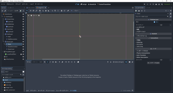
This time, let’s place tiles using the TileMapLayer named “Base”. Please select Base.
A window titled “Tile Map” appeared at the bottom, but it contains some English text. It says, “No TileSet found, please create a TileSet in the Inspector.”
Create a “TileSet”
What is a TileSet? It is a configuration for basic information such as the size and shape of tiles handled by this TileMapLayer node, and whether they collide with characters.
The image prepared earlier for tiles is a 48x48 square, and since it serves as a platform for characters, it is a tile that collides with characters. Let’s create a TileSet to match this.
-
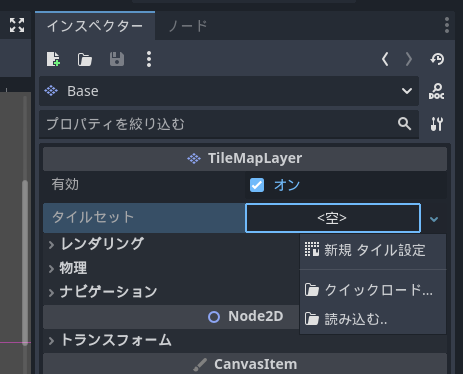
Click **<Empty>** in the TileSet section of the Inspector and select **"New TileSet"**.
-
You can edit the contents of the TileSet settings. Configure them as follows:
Tile Shape: Square
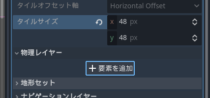
Tile Size: x = 48px, y = 48px

-
Expand the Physics Layer and press the **[+ Add Element]** button.
-
A section called Collision Layer/Collision Mask will appear, but no changes are needed. If you end up with the following state, the TileSet configuration is complete.

Note: About Collision Layer and Collision Mask
In Godot, this section determines whether nodes can collide with each other. Collision Layer indicates the group to which a node belongs, and Collision Mask specifies which groups it wants to collide with.
This will be explained in detail in the next Chapter 3.
Configure “Tile Settings”
Once the TileSet creation is complete, the message in the bottom window changes to “No source for TileSet”. This means you cannot place tiles because no image has been set for the tiles.
Next, you need to set the tile image to the previously downloaded tile.png and define the collision shape (wall detection) for the tiles using polygons.
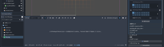
- Switch the tab at the very bottom from “Tile Map” to “Tile Set”.

- Drag and drop tile.png from the File System window into the black box on the left side of the “Tile Set” window.

- A new window will pop up. Since this TileSet is a 48px square, set the Tile Size item to x:48 y:48 and click “Yes”.

Note: What is an Atlas?
An Atlas is a single large image file that combines various types of images. Game engines have a mechanism to efficiently display images by extracting and showing only a portion of a large image file. Since we only have one type of tile in this case, creating an Atlas is not necessary. However, if you want to handle tiles of various shapes simultaneously, such as floors, walls, air, and slopes, grouping them into one large image allows for more efficient display than handling multiple small images.
-
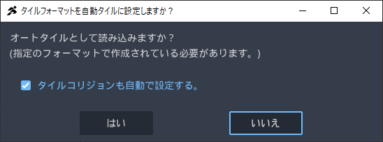
Next, a window asks, **"Do you want to load as an Autotile?"**
ACTION GAME MAKER provides a mechanism called Autotile, which automatically changes tiles based on placement and connectivity for atlases arranged in a specific format. However, since we only have one tile, this cannot be used. Please click “No”.
-
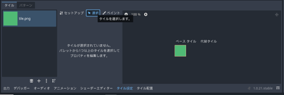
If the Tile Set configuration looks like the display below, it is successful. Next, we will create the wall detection shape.

-
Click **"Select"** at the top center of the Tile Set window to switch tabs. **This tab is used to perform detailed settings for the selected tile**.
-
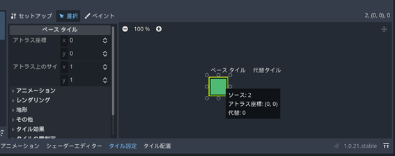
**Click the tile displayed on the right side of the window**. The bottom of the "Select" tab will change to a display similar to the Inspector.
-
Scroll down in the Select tab and **open "Physics" > Physics Layer 0 at the very bottom**. Physics Layer 0 is the physics layer created earlier in the Tile Set settings.

-
From here, **we will draw the wall detection using the Polygon Tool**. **Click the icon with a square and a plus sign (Add Polygon Tool)**. This is a tool to add vertices for drawing polygons. A polygon is a system for drawing shapes by enclosing them with points.

-
Once selected, click the top-right corner of the green square. A ◇ indicating a polygon vertex should appear.

-
Similarly, **add points to the four corners in a clockwise direction: bottom-right, bottom-left, and top-left**. -
Finally, click the already added point at the top-right again. The green tile should turn orange. This indicates that the area enclosed by the vertices = the entire tile has become a wall detection area.

Troubleshooting
If the vertex positions are misaligned: You can move the points using the tool with a square and an arrow icon (Edit Point Tool).
If you created an extra vertex and it became a pentagon: You can delete the point using the tool with a square and an X mark (Delete Point Tool).

