第2章:簡単なステージを作ろう!
第2章の目標
ここからは、実際にアクションシューティングゲームの作成に取り掛かります。
この章では、以下のことが可能な簡単なステージの作成プロセスを解説します。
この章が終わる頃には、以下に示すような例のようなものが完成しているはずです。
ワークフロー
-
まず、ステージそのもののシーンが必要です。
-
そのステージの中に、キャラクターが移動やジャンプができるプラットフォームを配置します。
-
次に、キャラクターのシーンを作成し、ビジュアルスクリプトを使用して移動機能を実装します。
「ゲームシーン」と「ゲームオブジェクト」について学ぶ
第1章では、Godot Engineの機能のみを使用してすべてを作成しました。
ここからは、ゲームを構築するためにACTION GAME MAKERの追加機能を使い始めます。
Godot Engineでは、通常、キャラクター、コース、その他の要素を、ルートノードにノードを一つずつ追加して作成します。しかし、これは非常に時間がかかることがあります。
これを簡単にするために、ACTION GAME MAKERは2つの主要なプリセットシーンを提供します。
-
ゲームシーン
- ゲームシーンは、ステージやコースに使用されるシーンです。
-
ゲームオブジェクト
- ゲームオブジェクトは、プレイヤー、敵、アイテム、および同様の要素に使用されるシーンです。
ACTION GAME MAKERでは、ゲームシーン内にゲームオブジェクトを配置することでゲームを作成します。
ACTION GAME MAKERによって追加された機能の見分け方
ゲームシーンやゲームオブジェクトなど、ACTION GAME MAKERによって追加された機能は、青とオレンジの2色アイコンでマークされています。
これらの色付きのノードやボタンが表示された場合は、それがACTION GAME MAKERの機能であることを意味します。
一方、元のGodotノードは単色アイコン(白、青、緑など)を使用しますが、いくつかは複数の色を使用する場合があります。
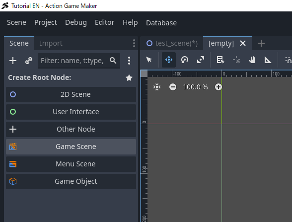
「ゲームシーン」の作成
それでは、ゲームシーンを設定していきましょう。
手順
-
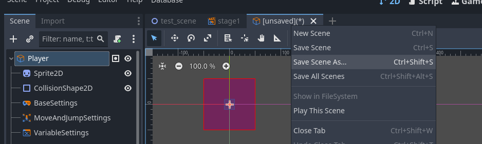
シーンタブで、**「+」(新規シーン追加)**ボタンをクリックします。
-
シーンウィンドウのルートノードの作成セクションで、ゲームシーンを選択します。
-
シーンウィンドウに多数のノードが自動的に表示されます。これらはゲームシーンを構成するプリセットノードです。
-
新しいシーンなので、保存しましょう。
-
これはステージ(コース)シーンなので、stage1.tscnとして保存します。
ゲームシーンの構造
突然多くのノードが追加されたことに気づかれたかもしれませんが、それぞれが具体的に何をするのでしょうか?
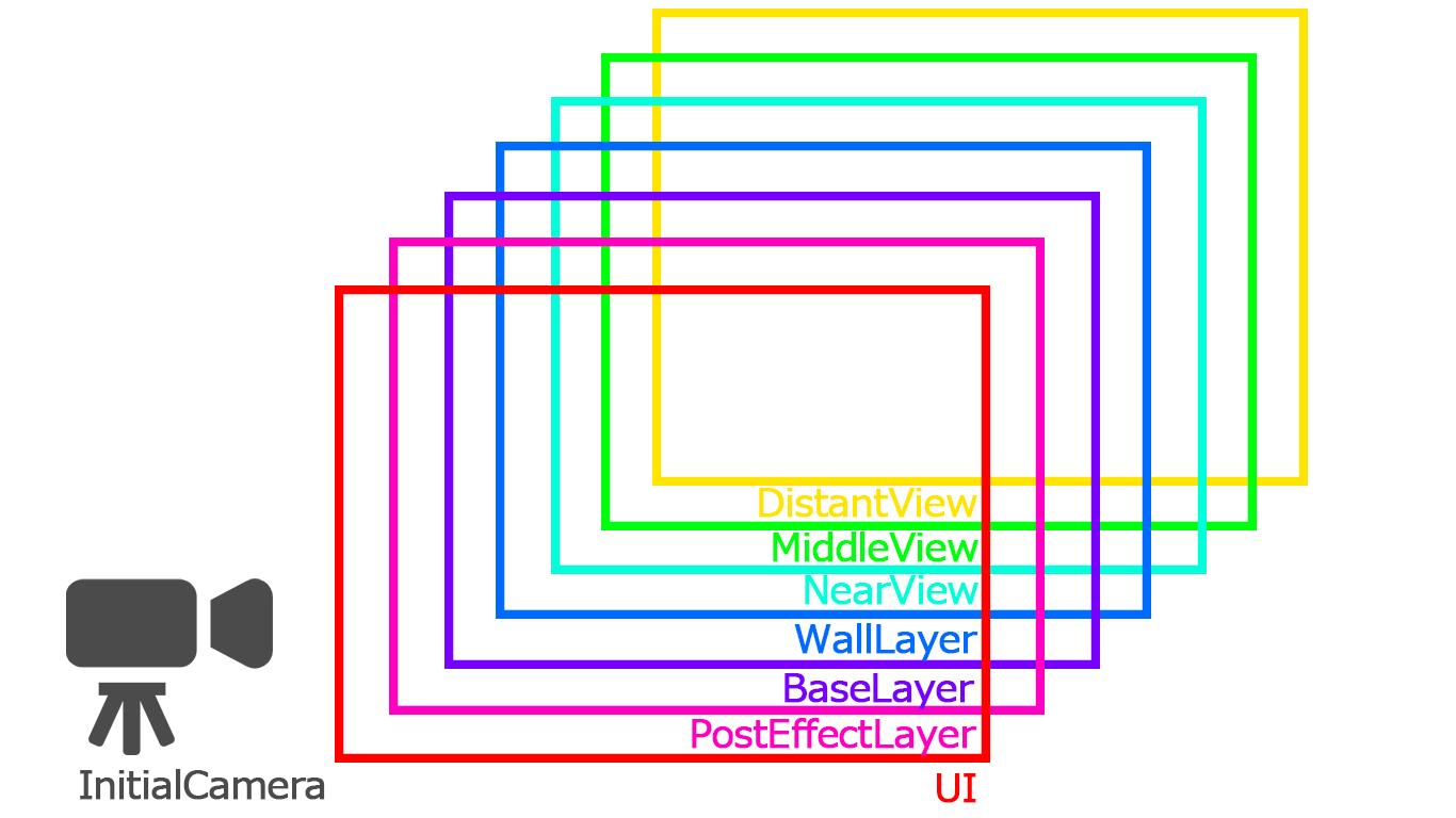
ACTION GAME MAKERでは、ゲームシーンは「レイヤー」という概念を用いて構成されています。
レイヤーとは、劇場の舞台のように奥行きを表す方法の一つです。
- 背景レイヤー(背景美術)が最も奥に位置します。
- キャラクターレイヤーは中央にあり、ここで俳優(キャラクター)が演技を行います。
- 前景レイヤーは手前にあり、観客に最も近い位置に小道具が配置されます。
「前方に設置されたカメラを通して」見た場合、これらのレイヤーが組み合わさってゲームのシーンが形成されます。
ACTION GAME MAKERには7つのデフォルトレイヤーが用意されています。それぞれ名前とアイコンが異なり、わずかに機能も異なりますが、図のように積み重ねられています。
デフォルトでは、各レイヤーに最低限必要なプリセットノードが既に配置されており、さらにシーン全体を捉える単一のカメラも用意されています。
「SceneLayer」ノードと「UI」/「PostEffectLayer」ノードの違い
7つのレイヤーのアイコンを詳しく見ると、いくつかの違いに気づくでしょう。大まかに分けると、2つのタイプがあります。
- SceneLayerノードの子要素である、BaseからDistantViewまでの5つのレイヤー。
- UIとPostEffectLayerの2つのレイヤー。
その違いは以下の通りです。
- SceneLayerノードは、カメラの位置によって見えるものが変化する、奥行きを持つ空間を表します。
- UIおよびPostEffectLayerノードは、カメラの位置に関わらず、常にカメラに表示されます。
劇場の例えを使うと:
- 舞台そのものがSceneLayerです。
- カメラレンズに装着されたフィルターがUIおよびPostEffectLayerです。
「初期シーン」の設定
ACTION GAME MAKER では、シーン管理に専用のシーン遷移システムを使用します。
このシステムを使えば、ビジュアルスクリプトに似た操作で、シーン同士をどのように接続するかを定義できます。
まず、ゲーム開始時に最初に表示されるシーンである初期シーンとして、今回作成したシーンを設定しましょう。
手順
-
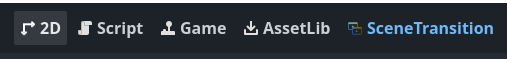
画面上部中央のボタンから、エディタモードをSceneTransitionに切り替えます。
- このボタンは、中央のエディタウィンドウに表示される内容を切り替えます。
-
空のグリッドが表示されます。
-
グリッド上にstage1.tscnが表示されていれば完了です。
-
画面上部中央のボタンから2Dモードに戻り、以前の表示に戻ります。
- これで、ゲーム開始時にstage1が最初のシーンとして表示されるようになります。
注意:初期シーンを設定しなかった場合
ACTION GAME MAKER では、常にcore.tscnという特別なシーンがバックグラウンドで実行されます。
通常、このシーンが指定されたゲームシーンをロードして表示します。
初期シーンを設定しない場合、core.tscnのみが表示されるため、ゲームは空の画面で起動することになります。
タイルの設定
さて、ステージのプラットフォームを作成していきましょう。
地面と、ジャンプするためのいくつかの浮遊プラットフォームが必要です。プラットフォームを作成するには、さまざまなノードを使う方法がありますが、今回は複数の形状を持つ広いステージを構築するため、この目的のために設計されたノードであるタイルを使用します。
タイルとは、床のタイルと同じように、小さな画像をグリッド状に繰り返してプラットフォームのような大きな構造を構築するものです。
FileSystem へのタイル画像のインポート
まず、タイル画像を用意しましょう。
提供された画像を右クリックして保存してください。

第 1 章で説明したように、Godot Engine はプロジェクトのFileSystem内に配置されたアセットのみで動作します。
FileSystem を、遊園地の資材が使用される前に保管される倉庫と考えてください。
インポート方法は簡単です。ファイルをエディタにドラッグ&ドロップするだけです。
-
ダウンロードした画像が入った PC のフォルダを開いたままにします。
-
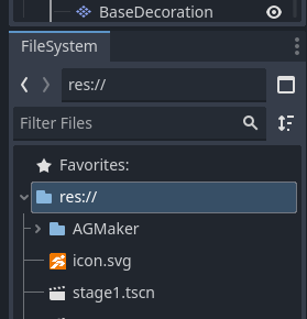
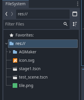
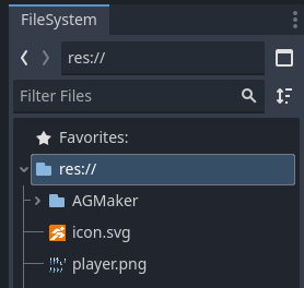
エディタで、FileSystem パネル(左下)に移動し、**res://**を選択します。
- インポートされたファイルは、選択したフォルダに保存されます。
-
PC のフォルダからtile.pngをエディタウィンドウにドラッグします。
タイルを配置するレイヤーの選択
次に、タイルを配置するレイヤーを決めましょう。
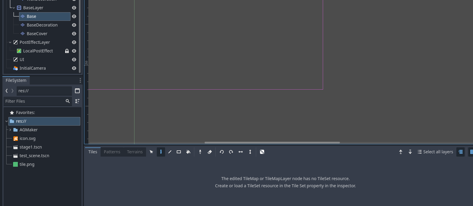
地面用のタイルを配置するためのデフォルトのレイヤーであるBaseLayerを使用します。
BaseLayer の中を見ると、Base、BaseDecoration、BaseCoverの 3 つのノードがあります。
これらは実際には名前が変更されたTileMapLayer ノードです。
なぜ同じノードが 3 つあるのでしょうか?
-
タイルを重ね合わせて奥行きを作成できるようにするためです。
-
例えば、地面のタイルの上に松明を置きたい場合があるでしょう。
-
レイヤーが 1 つしかない場合、松明を置くと地面のタイルが上書きされてしまいます。
-
レイヤーが複数ある場合、それらを重ねて地面と装飾の両方を見せることができます。
今回は、タイルを配置するためにBaseという名前のノードを選択します。
下部には、以下のようなメッセージが表示されたパネルがあります:
「TileSet が見つかりません。Inspector で TileSet を作成してください。」
TileSet の作成
TileSetは、この TileMapLayer ノードで使用するタイルの基本情報を定義します。
-
各タイルのサイズと形状
-
キャラクターがそれと衝突できるか、通過できるか
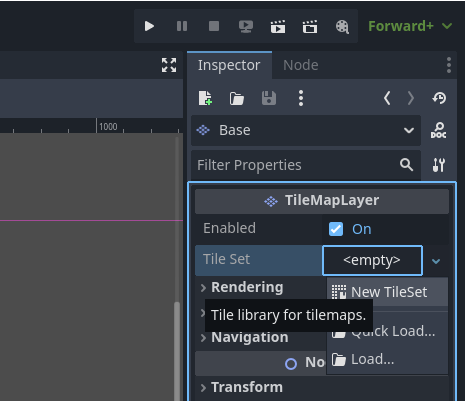
用意したタイル画像は 48×48 ピクセルの正方形です。プレイヤーが立つプラットフォームとして機能するため、衝突を有効にする必要があります。
-
Inspectorで、TileSetの隣にある****をクリックし、New TileSetを選択します。
-
これで TileSet のプロパティを編集できます。以下のように設定します。
-
Physics Layersセクションを展開し、+ Add Elementをクリックします。
-
Collision Layer / Collision Maskはデフォルトのままにします。
注:衝突レイヤーとマスク
Godot では、衝突は 2 つの設定によって決定されます。
これについては第 3 章で詳しく説明します。
タイルの設定
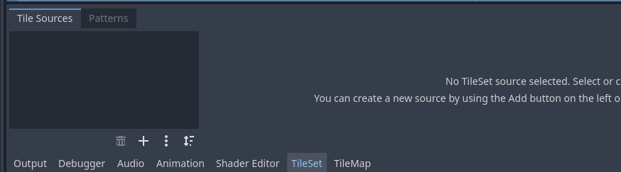
TileSet を作成すると、下部のメッセージが以下のように変わります:
「TileSet のソースがありません」。
これは、タイル用の画像をまだ割り当てていないことを意味します。
また、それらのための衝突形状(壁/床)を設定する必要があります。
-
下部パネルで、タブをTileMapからTileSetに切り替えます。
-
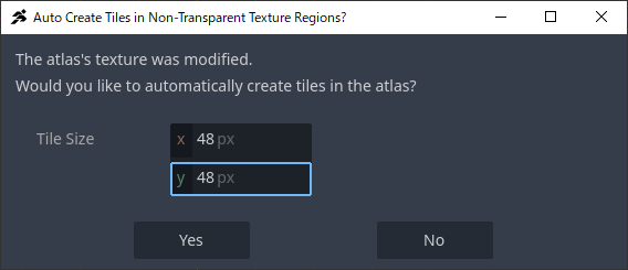
FileSystem パネルからtile.pngを、TileSet エディタの左側の黒いボックスにドラッグします。
-
新しいウィンドウが表示されます。タイルが 48×48 の正方形なので、Tile Size: x=48, y=48に設定し、Yesをクリックします。
-
次のウィンドウで「Tile Format を Auto Tile に設定しますか?」と尋ねられます。Noを選択してください。
注:アトラスと Auto Tile とは何か
アトラスとは、多くの小さな画像(床、壁、斜面など)を含む単一の大きな画像ファイルのことです。
個々の画像ファイルを多数扱う代わりに、エンジンが 1 つの大きな画像を読み込んでそれをタイルにスライスします。これにより効率が向上します。
Auto Tileは、ACTION GAME MAKER に固有の機能の 1 つです。
特定の形式で配置されたタイルアトラスを自動的に整然と配置しますが、今回は使用しません。
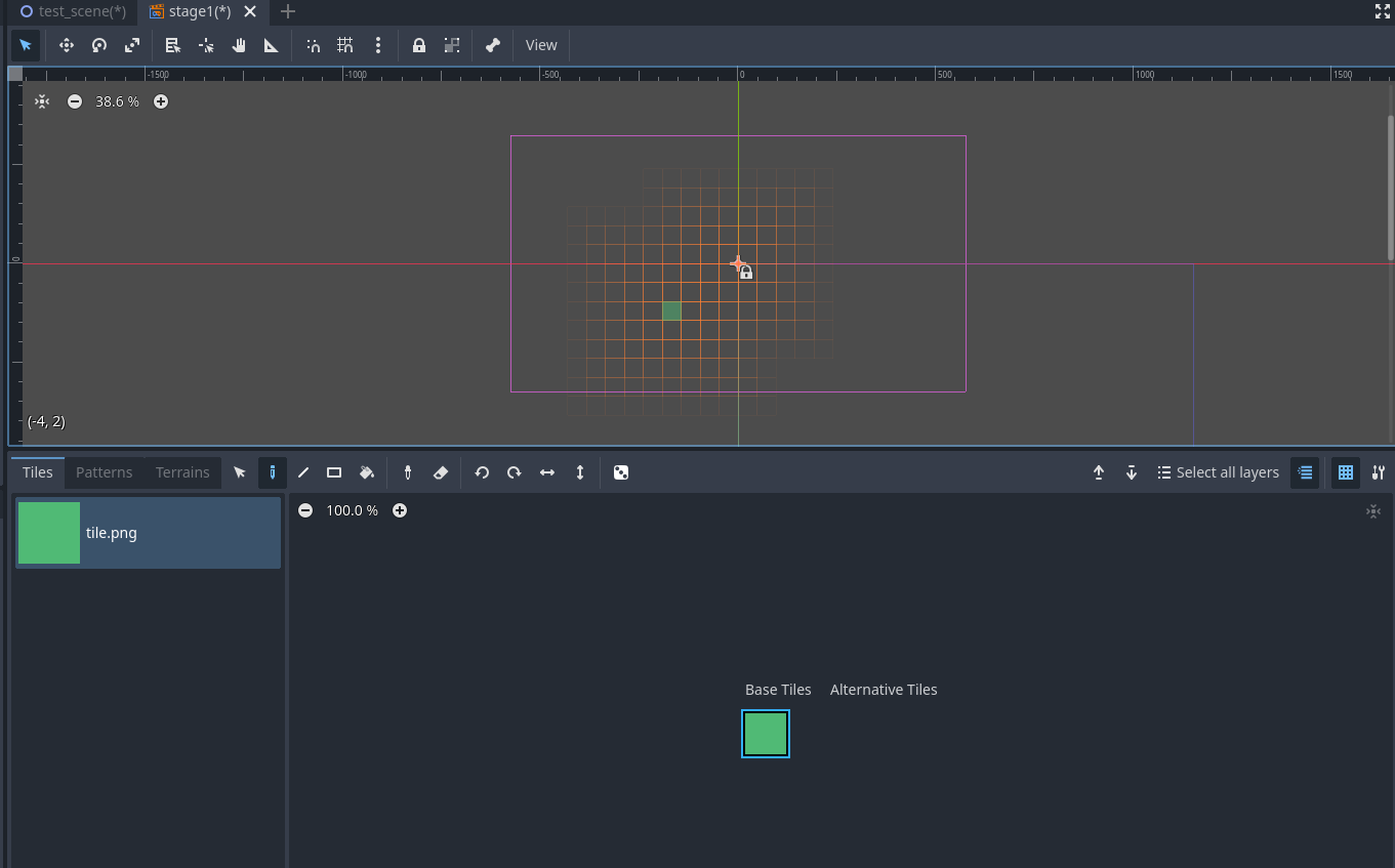
タイルへの衝突形状の追加
-
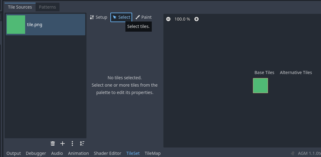
TileSet エディタで、上部のSelectタブに切り替えます。
- このタブでは、個々のタイルの詳細設定を構成できます。
-
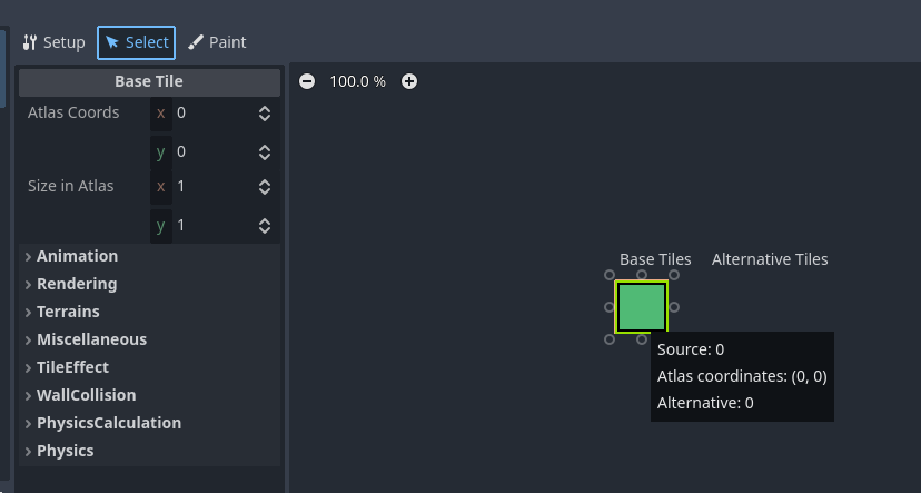
右側で、タイル画像をクリックして選択します。
-
下にスクロールして、Physics > Physics Layer 0を開きます。
-
Add Polygon Toolボタン(「+」アイコン付きの四角形)をクリックします。
-
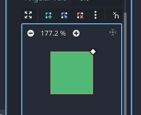
緑色の正方形の右上隅をクリックします。ダイヤモンド型の点が表示されます。
-
同じように、右下、左下、左上の隅を時計回りにクリックします。
-
最後に、最初に配置した点(右上)を再度クリックします。
- タイルがオレンジ色に変わり、正方形全体が衝突領域としてマークされたことが示されます。
トラブルシューティング
 この段階で、タイルのインポート、TileSet の作成、画像の割り当て、プラットフォームとして機能するための衝突設定が正常に完了しました。
タイルの配置
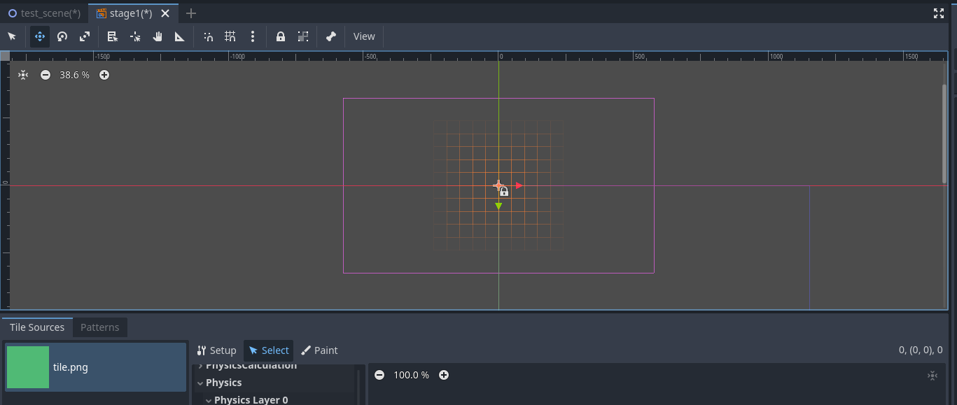
タイルの準備が整ったので、配置していきましょう。
カメラの可視範囲内に床といくつかのプラットフォームを作成するのが目標です。
手順
-
画面中央にあるエディタビューを確認します。
-
赤と緑の線が交差する点を中心に、薄い紫色の線で長方形が表示されているはずです。
-
この紫色の長方形はカメラの可視領域を表しています。
-
まず、カメラ領域が完全に映るようにビューを調整します。
-
エディタビューで、マウス中央ボタン(ホイールクリック)を押し続けます。
-
下部パネルで、タブをTileMap(タイルペイント)に戻します。
-
下部パネルの右側にあるタイルをクリックして選択します。
-
マウスをエディタビューに移動させると、カーソルの下にタイルのプレビューが表示されます。
-
以下の例のように、床とプラットフォームを描画します。
- 正確である必要はありませんが、プラットフォームが高すぎると、プレイヤーのジャンプでは届かない場合があります。
テストプレイでの確認
ゲーム内でどのように見えるか確認しましょう。
トラブルシューティングチェックリスト
タイルが期待通りに表示されない場合は、以下を確認してください。
入力マップ(操作)の設定
シンプルなステージが完成したので、次は通常通りプレイヤーキャラクターを作成するところですが、その前に**入力マップ(操作)**を設定しましょう。
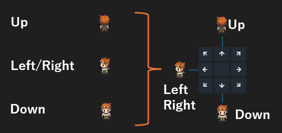
入力マップでは以下を定義できます:
- 「このボタンまたはキーが押されたとき、このアクションを実行する」
このチュートリアルでは、基本的な移動のみを含むシンプルなアクションシューティングゲームを作成します。
現時点では、以下の 4 つのアクションのみが必要です:
(後でスライディング、武器選択、梯子の登りなどのアクションを追加するかもしれませんが、まずは最低限のものだけ作成します。)
手順
-
左上のプロジェクトメニューからプロジェクト設定を開きます。
-
ウィンドウが表示されます。上部のタブを一般から入力マップに切り替えます。
-
「新しいアクションを追加」と表示されたフィールドに名前を入力します。
-
Right と入力し、右側の**+ 追加**ボタンを押します。
-
同じ手順を繰り返して、以下のアクションを追加します:
-
次に、アクションRightの右端にある**「+」ボタン(イベントを追加)**をクリックします。
-
「Right にイベントを追加」というタイトルのウィンドウが表示されます。キーボードの**→(右矢印)**キーを押します。
-
Right または Right (Physical) または Right(Unicode) と表示されていれば成功です。OKをクリックします。
-
他のアクションについても同じ手順を繰り返します:
-
最後に、閉じるボタンをクリックして終了します。
「ゲームオブジェクト」シーンの作成
それでは、ゲームオブジェクトのシーンを作成しましょう。
手順
-
Stage1を作成したときと同様に、エディタ上部の**「+」(新規シーン追加)**ボタンをクリックします。
-
ルートノードの作成の下で、Game Objectを選択します。
-
新規ゲームオブジェクトの作成ウィンドウが表示されます。
ACTION GAME MAKERでは、テンプレートからさまざまなオブジェクトを作成できます。
以下のように設定します。
-
オブジェクト名: Player
-
テンプレート: characters
-
タイプ: 2DSprite Character Base
-
オブジェクトグループ: Player
-
入力デバイスによって操作されるオブジェクト: On
-
CameraTargetSettings ノードを追加: On
-
複数のノードを含む新しいシーンが生成されます。
-
シーンに名前を付けて保存します。ここでは単純にplayer.tscnとして保存します。
ゲームオブジェクトの構造を理解する
一見すると、ゲームオブジェクト内の多数のノードは圧倒的に感じられるかもしれません。
しかし、これらのノードは大きく分けて3つのカテゴリに分類できます。
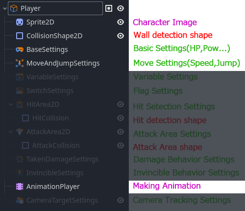
1. 名前に「Settings」が含まれるノード
これらのノードは、ACTION GAME MAKER のビジュアルスクリプトでアクセスして使用できるデータを格納します。
ここでHP、攻撃力、移動速度、ジャンプ力などの値を設定することで、ビジュアルスクリプト内でそれらを利用可能にします。
2. 名前に「Collision」が含まれるノード
これらのノードは、衝突判定に使用される形状を定義します。例えば:
- CollisionShape2D → 壁や床との衝突
- AttackCollision → 攻撃のヒットボックスの形状
- HitCollision → 被ダメージ時の判定形状
3. アニメーション関連のノード
- AnimationPlayer → キャラクターのアニメーションを制御
- Sprite2D → そのアニメーションで使用される画像を提供
ゲームオブジェクトを設定する際は、これら3つのグループのノードを使用することになります。
ビジュアルスクリプトはゲームオブジェクトでのみ設定可能
ACTION GAME MAKER のビジュアルスクリプトは、これらのノードからデータを読み取ることで動作します。
そのため、ビジュアルスクリプトはGameObject ノード(この場合はPlayerノード)にのみ割り当てることができます。
オブジェクト設定の計画
このセクションでは、移動とジャンプの設定のみを行います。
つまり、現時点では攻撃やダメージの設定は不要です。
現在必要なのは以下の要素のみです。
- プレイヤーの画像
- 移動とジャンプのアニメーション
- 移動速度
- ジャンプ力
- 移動キー
したがって、このパートではこれらの要素のみを設定します。
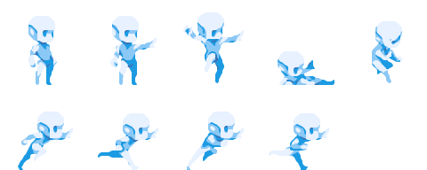
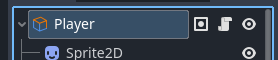
Sprite2D にプレイヤーのスプライトを設定する
プレイヤーの画像を、画像を表示するために使用されるSprite2Dノードに適用しましょう。
このチュートリアルでは、提供された画像を使用します。
手順
-
下の画像を右クリックして、コンピュータに保存します。
-
ダウンロードした画像をファイルシステムにドラッグ&ドロップしてインポートします。
-
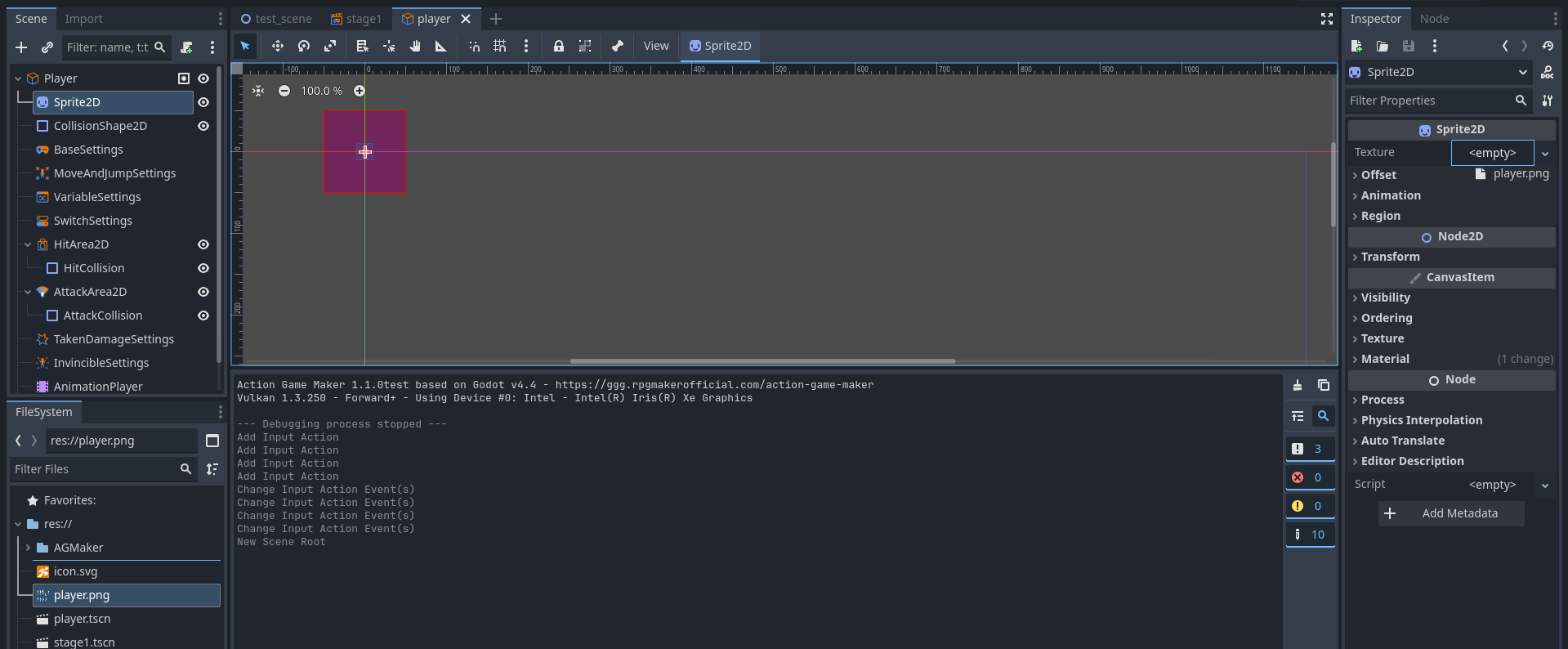
画像を表示するSprite2Dノードを選択します。
-
右側のインスペクターパネルで、Textureプロパティ(現在は<empty>に設定されています)を探します。
インポートしたplayer.pngファイルをそこにドラッグ&ドロップします。
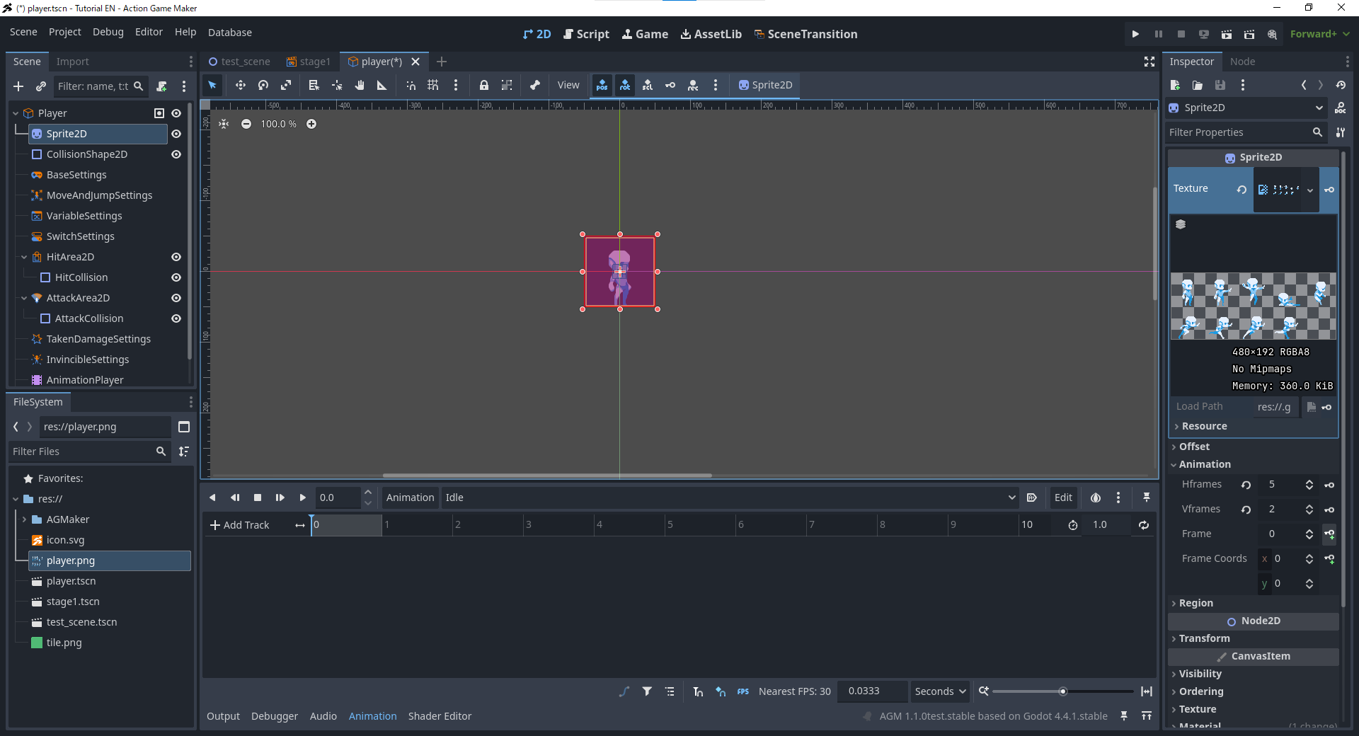
-
画像が表示されますが、9 文字すべてが一度に表示されていることに気づくでしょう。
スプライトシートの分割
-
インスペクターでAnimationセクションを展開します。
-
Hframes(水平フレーム)を5に、Vframes(垂直フレーム)を2に設定します。
-
インスペクターでFrameプロパティの上下矢印をクリックして試してみましょう。
注意:なぜ最初のフレームは 0 から始まるのか?
最初のフレームが1ではなく0としてラベル付けされているのが奇妙に思えるかもしれません。
プログラミングでは、リストは通常0から始まります。
Godot も同じ慣習に従っているため、フレーム番号も0から始まります。
AnimationPlayer ノードを使用したアニメーションの作成
Godot Engine / ACTION GAME MAKER では、AnimationPlayer ノードを使用してアニメーションを作成します。
このシステムは、ビデオ編集のようなタイムラインベースのスタイルで動作します。
タイムライン上では、トラック(画像、音声など用)を作成し、キーフレーム(イベント)を配置します。時間が経過するにつれ、AnimationPlayer は各トラック上のキーフレームを実行します。
これはオーケストラの楽譜のようなものだと考えてください:
- 1 秒の時点で、ピアノが C の音を演奏します。
- その瞬間、バイオリンが D の音を演奏します。
この例えでは:
- トラック = 楽器
- キーフレーム = 演奏方法の指示
必要なアニメーション
このチュートリアルでは、3 つの基本的なアニメーションを作成します:
- Idle(待機) → 入力がないとき
- Jump(ジャンプ) → ジャンプボタンが押されたとき
- Move(移動) → 左右の入力があったとき
これらすべてのアニメーションをAnimationPlayerを使用して作成します。
手順
-
シーンパネルでAnimationPlayerノードを選択します。
-
下部に新しいアニメーションパネルが表示されます(以前のタイルエディタと同様)。
-
アニメーションボタンをクリックし、新規を選択します。
-
アニメーション名を入力するウィンドウが表示されます。まずはIdleから始めます。名前を入力してOKを押します。
-
Idle アニメーションが作成されました。
- 以前設定したスプライトフレームを使用してアニメーションを構築します。
-
Sprite2Dノードを選択します。
-
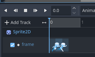
インスペクタのアニメーション > フレームで、0に設定されていることを確認します。
-
ウィンドウが表示されます。「RESET トラックの作成」をオフにしてから、作成を押します。
補足:RESET トラックとは?
RESET トラックは、シーンの初期状態を指定します。
例えば、Idle ではこれをデフォルト状態として設定することもできます。
ただし、ACTION GAME MAKER では通常これを使用しないため、オフのままにしてください。
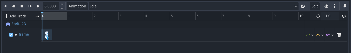
-
タイムラインにSprite2D: frameというトラックが表示されます。
- 0 秒の時点で、player.png のフレーム 0 が設定されます。
- Idle アニメーションが始まると、即座にこの画像が表示されます。
- Idle は 1 枚の画像のみを使用するため、これで完了です。
-
ステップ 1~8 を繰り返して、Jumpアニメーションを作成します。
- 最後に、Moveアニメーションを作成します。
Move アニメーションの作成
-
前述の通り、Moveという名前の新しいアニメーションを作成します。
-
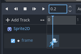
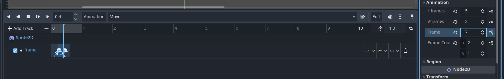
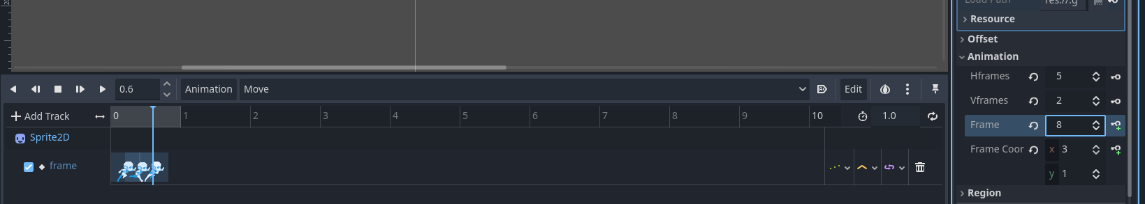
タイムラインのプレイヘッドを0.2 秒に移動します(時間表示のボックスに「0.2」と入力します)。
-
Sprite2D のフレームを6に変更し、 + ボタンを押してキーフレームを挿入します。
- 同じ手順を繰り返します:
- アニメーションの長さを調整します。
-
アニメーションパネルの右上に、1(デフォルトの秒数)が表示されているボックスがあります。
-
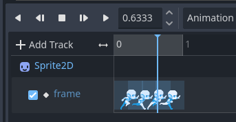
これを0.8に変更します。4 つのフレームを 0.2 秒ずつ使用するためです。
-
これにより、アニメーションがスムーズにループします。
- ループを有効にします。
補足:ループとピンポンループの違い
- すべて設定できたら、再生ボタンを押してアニメーションをテストします。
トラブルシューティング
-
アニメーションがおかしい場合:
-
トラック上の各フレームを選択し、値フィールドを確認します。
-
順序が5 → 6 → 7 → 8になっていることを確認します。
-
違っている場合は、手動で数字を変更して修正します。
-
以下を再確認してください:
-
アニメーションがループ設定になっていること。
-
長さが0.8 秒に設定されていること。
これで、プレイヤーキャラクター用のIdle(待機)、Jump(ジャンプ)、**Move(移動)**アニメーションの作成が完了しました。
アニメーションセットの作成
ACTION GAME MAKER には、移動方向に応じて自動的にアニメーションを切り替える「Animation Set(アニメーションセット)」というシステムがあります。
アニメーションセットに最大 8 方向分のアニメーションを割り当てることで、そのセットを一度選択するだけで、右、左、上などに移動した際にアニメーションが自動的に切り替わります。
今回のゲームでは、移動方向は右と左の 2 方向のみで十分です。
現在、Idle(待機)、Jump(ジャンプ)、Move(移動)の 3 つのアニメーションしかありませんが、これらはすべて右を向いています。
ただし、アニメーションを自動的に反転させるオプションがあり、これはデフォルトで有効になっています。
つまり、左を向いたアニメーションを別途作成する必要はなく、システムが自動的に反転(ミラー)処理を行ってくれます。
また、このように左右の移動のみが必要で、右向きのアニメーションを反転させられるような場合は、一括読み込み機能を使ってアニメーションセットを素早く設定できます。
手順
-
Scene パネルで、Player ノード(GameObject ノード)を選択します。
-
Inspectorで、Select Animation Playerと書かれたボタンをクリックします。
-
ノード選択ウィンドウが表示されるので、AnimationPlayerノードを選択します。
-
次に、Bulk Load Animationsボタンをクリックします。
-
正常に動作したか確認するために、Animation Setセクションを展開します。
-
成功すると、Animation Set の中にJump、Idle、Moveのアニメーションがリストされているはずです。
トラブルシューティング
-
アニメーションがセットに表示されない場合:
- Assign AnimationPlayerに戻り、AnimationPlayer ノードを再度割り当ててください。
プレイヤー設定の調整
アニメーションを作成したので、次にプレイヤーの設定を行います。
以下の 3 つの作業が必要です。
- 移動に使用するキーを設定する
- 移動速度とジャンプ力を調整する
- キャラクターの体に合わせるよう衝突形状のサイズを変更する
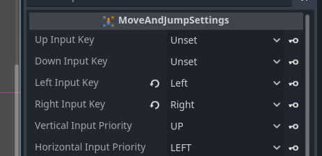
移動キーの設定
以前に設定した入力アクションを使用して、移動キーを割り当てましょう。
-
シーンパネルで、MoveAndJumpSettingsノードを選択します。
-
インスペクターで以下を設定します。
-
Left Move Key → Left
-
Right Move Key → Right
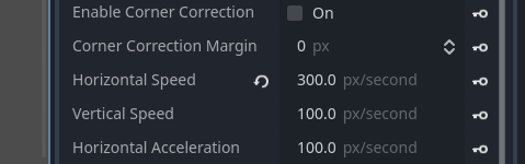
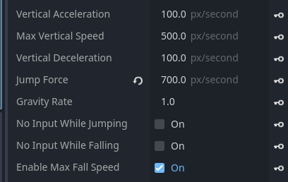
移動速度とジャンプ力の調整
次に、キャラクターに適した値に速度とジャンプ力を調整しましょう。
-
MoveAndJumpSettingsノードが選択された状態で、インスペクターを確認します。
-
Horizontal Speedの値を100から300に変更します。
-
下部にあるJump Forceというプロパティを見つけます。
衝突形状の調整
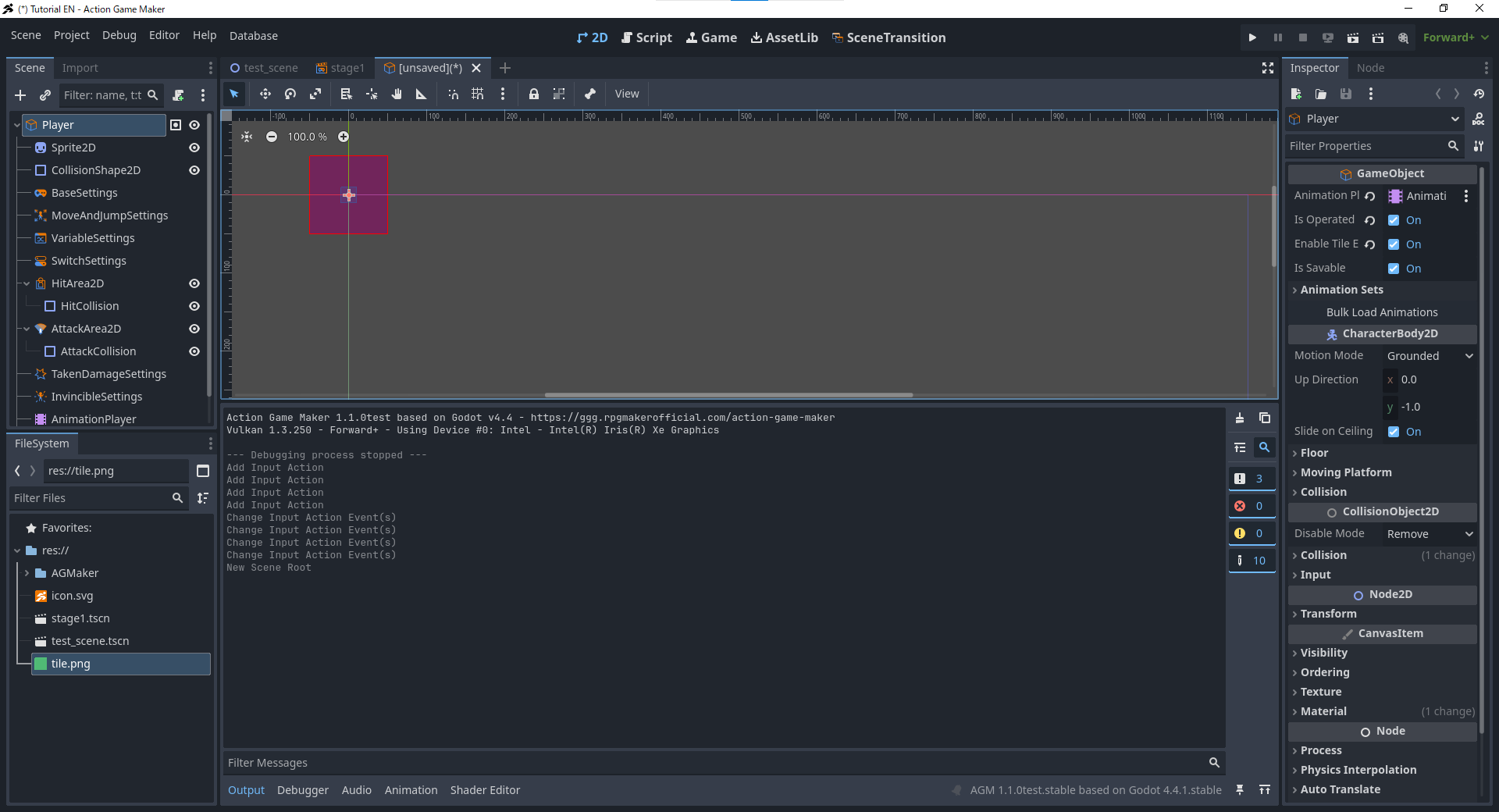
CollisionShape2Dノードは、キャラクターが地面や他の物体と衝突する際の形状を定義します。
現在、この形状が小さすぎます(キャラクターの頭よりも小さいため、体が地面に沈み込んでしまいます)。
スプライト全体に合うようにサイズを変更しましょう。
-
シーンパネルで、CollisionShape2Dノードを選択します。
 キャラクターが現在JumpまたはMoveのフレームを表示している場合は、AnimationPlayerをIdleに戻してください。
-
四隅にあるオレンジ色の点をクリックしてドラッグし、長方形のサイズを変更します。
完了すると、プレイヤーは入力に正しく反応し、適切な速度で移動・ジャンプできるようになり、地面に沈むことなく衝突するようになります。
ビジュアルスクリプトでキャラクターを移動させる
すべての準備が整いました。これでビジュアルスクリプトを使用して、プレイヤーキャラクターを移動させましょう。
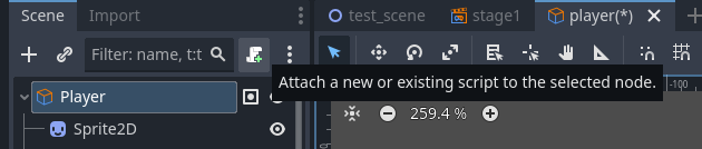
まず、ビジュアルスクリプトをプレイヤーにアタッチ(追加)します。
ビジュアルスクリプトのアタッチ
-
シーンパネルで、Player ノード(GameObject)を選択します。
-
** +(スクリプトのアタッチ)**ボタンをクリックします。
-
新しいウィンドウが表示されます。VisualScript(ビジュアルスクリプト)かGDScript(標準のプログラミングスクリプト)のどちらをアタッチするかを尋ねます。
-
エディタビューが自動的にScript タブに切り替わります。
前のビューに戻る
前の画面に戻りたい場合は、上部のタブを2Dに切り替えるだけです。
シーンの遷移セクションで説明した通り、上部のタブはエディタに表示する内容の切り替えに使用されます。

ステートの作成
必要なステートの決定
第1章で説明した通り、ACTION GAME MAKER のビジュアルスクリプトは以下の手順で作成されます:
- キャラクターのステートに動作を追加し、
- 条件付きでそれらのステートを相互に接続(リンク)します。
今回は、キャラクターがステージ上を歩き回り、ジャンプするだけのゲームであるため、以下の3つのステートだけで十分です:
これら3つのステートを接続し、適切な条件で切り替えることで、プレイヤーの移動を実現できます。
まずはアイドル、移動、ジャンプの各ステートを準備し、アニメーションと動作を割り当てていきましょう。既存のState001をアイドルステートとして再利用できます。
アイドルステートの作成
-
スクリプトウィンドウでState001を選択します。
-
インスペクターでタイトルを「State001」からアイドルに変更します。
-
割り当てるアニメーション > アニメーション選択の下にある空欄をクリックし、アイドルを選択します。
- これで、キャラクターがアイドルステートにある間、アイドルアニメーションセットが再生されます。
移動ステートの作成
移動ステートは新しいステートとして作成する必要があります。
-
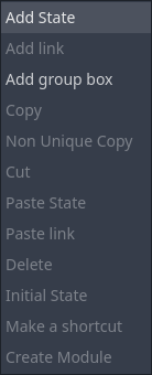
アイドルステートの右側の空白スペースを右クリックします。
-
メニューからステートの追加を選択します。
-
新しい「State001」が表示されるので、タイトルを移動に名前変更します。
-
アニメーションカテゴリで移動を選択します。
- これで、キャラクターが移動ステートにある間、移動アニメーションが再生されます。
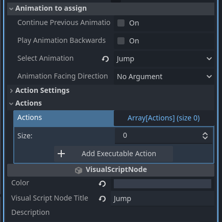
ジャンプステートの作成
ジャンプステートには、アニメーションとジャンプ動作の両方が必要です。
-
アイドルと移動のステートの下に新しいステートを作成します。
-
以前と同様に、タイトルをジャンプに名前変更し、アニメーションをジャンプに設定します。
-
アクション設定セクションを展開します。
補足:なぜ移動ステートには「移動動作を実行」のようなアクションがないのか?
プレイヤー入力に基づく移動は、MoveAndJumpSettingsで設定したキーバインディングによって既に処理されています。
このシステムはすべてのステートに適用されるため、移動ステートには移動のための追加アクション設定は不要です。
これで、アイドル、移動、ジャンプという3つの主要なステートが設定され、キャラクターの動作を制御する準備が整いました。
状態をリンクで接続する
3 つの状態を作成したので、プレイヤーがスムーズに状態間を遷移できるよう、リンクでそれらを接続しましょう。
遷移条件について考える
このゲームの基本的なロジックは以下のようになります。
- 左/右入力が押された場合 → 移動
- ジャンプ入力が押された場合 → ジャンプ
- 入力がなかった場合 → 待機
つまり:
- 待機 → 移動:左/右が押された場合、移動 → 待機:入力がなくなった場合。
- 待機 → ジャンプ:ジャンプが押された場合、移動 → ジャンプ:移動中にジャンプが押された場合。
- ジャンプ → 待機:地面に接触したとき(タイルと下方で衝突したとき)。
 ジャンプ → 移動のリンクも必要でしょうか?
必ずしも必要ありません。移動キーを押しながら着地した場合、待機 → 移動への遷移が即座に起こるため、直接ジャンプ → 移動のリンクは不要です。
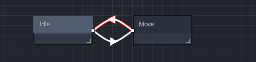
待機と移動のリンク
-
待機状態を右クリックし、リンクの追加を選択します。
-
線を待機から移動状態にドラッグします。
- これで待機と移動が接続されました。
- 次に、条件を追加します:左/右が押されたら移動へ遷移する。
-
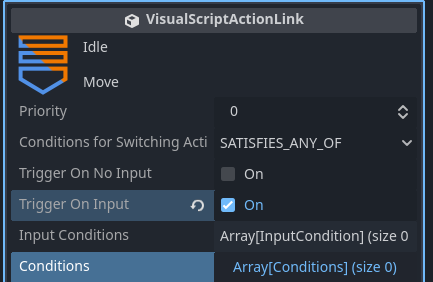
新しいリンクを選択します。インスペクターで**「入力時にトリガー」**をチェックします。
-
新しい**入力操作リスト (Array[InputCondition])**を展開します。
-
+ 入力の追加をクリックします。
-
新しい<empty>スロットが表示されます。それをクリックし、新しい入力条件を選択します。
-
<empty>が入力条件に変わります。クリックして展開します。
-
以下の通りフィールドを設定します:
-
入力ターゲット: 4 つの任意の入力キー
-
上キー: なし
-
下キー: なし
-
左キー: 左
-
右キー: 右
-
入力方法: 押されている
-
これで、キャラクターは左または右が押されているときに待機 → 移動へ遷移します。
-
次に、移動 → 待機のリンクを作成しましょう。移動を右クリックし、リンクの追加を選択します。
-
新しいリンクを選択します。
-
インスペクターで**「入力がない場合にトリガー」**をチェックします。
- これで、キーが押されていないときにキャラクターが待機状態に戻ります。
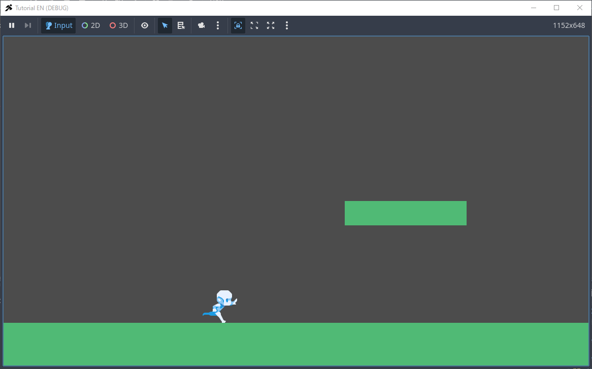
プレイヤーをステージに配置してテスト
この時点で、プレイヤーは地面を左右に歩けるはずです。
stage1.tscnにプレイヤーシーンを入れてテストしましょう。
-
エディタのビューをスクリプトから2Dに切り替えます。
-
プレイヤーシーンを保存します:player タブを右クリックし、シーンの保存を選択します。
-
stage1.tscnタブに切り替えます。
-
シーンパネルで**Base (TileMapLayer)**を選択します。
-
ファイルシステムからplayer.tscnをステージにドラッグし、地面に配置します。
-
プレイヤーがBaseLayer の子として表示されていることを確認します。
- 間違ったレイヤーにある場合は、シーンパネル内でドラッグして修正します。
- 位置がおかしい場合は、移動モードを使用して調整します。
-
右上の**プロジェクトを実行 (F5)**ボタンをクリックします。
-
すべてが正しければ、キャラクターは以下のようになります:
- 左/右が押されたときに歩く
- キーを離したときに止まる
トラブルシューティング
- プレイヤーが動かない → MoveAndJumpSettings に正しい入力キーが割り当てられているか確認してください。
- プレイヤーは動くがアニメーションが変わらない → 待機 → 移動のリンクと、移動状態のアニメーション設定を確認してください。
- プレイヤーが待機状態に戻らない → 移動 → 待機のリンク条件が正しいか確認してください。
エラー:ID is not set in CameraTargetSettings.
この警告は、CameraTargetSettings が存在するが設定されていないことを意味します。
カメラ追跡は第 4 章で設定するため、このエラーは現在無視して問題ありません。
待機、移動、ジャンプのリンク
次に、ジャンプを他の状態に接続しましょう。
-
playerタブに戻り、エディタをスクリプトビューに設定します。

-
待機を右クリックし、リンクを追加してジャンプに接続します。
-
リンクを選択し、**「入力時にトリガー」**を有効にします。
-
入力リストを展開 → + 入力の追加 → 新しい入力条件。
-
以下のように設定します:
-
次に、移動 → ジャンプをリンクします。
- 条件が同じであるため、待機 → ジャンプのリンクを再利用できます。
-
待機 → ジャンプのリンクを右クリックし、コピーを選択します。
-
移動状態を右クリックし、リンクの貼り付けを選択します。
-
新しい線を移動からジャンプにドラッグします。
-
移動 → ジャンプのリンクを選択し、正しく設定されているか(ジャンプキーが押されている)確認します。
ジャンプから待機へのリンク
-
ジャンプ状態を右クリックし、リンクを追加して待機に接続します。
-
これは入力ベースではないため、インスペクターを開き、+ 条件の追加をクリックします。
-
ウィンドウが表示されます。ContactWithTileを選択します。
-
条件で、Incoming Contact Direction → Bottomを設定します。
これは、プレイヤーの下部がタイル(地面)に触れている場合のみを意味します。
-
リンクがこの設定になっている場合、完了です。
テストプレイ
**プロジェクトを実行 (F5)**をクリックします。
- 待機中または移動中にZを押すと、プレイヤーがジャンプします。
- 着地すると、プレイヤーは待機状態に戻ります。
トラブルシューティング
- ジャンプできない → 待機 → ジャンプと移動 → ジャンプのリンクを確認し、ジャンプ状態のジャンプアクションが有効になっているか確認してください。
- 着地できない → ジャンプ → 待機のリンクを確認し、「ContactWithTile (Bottom)」条件が設定されているか確認してください。
これで、Visual Script を使用してプレイヤーが待機、移動、ジャンプをスムーズに行えるようになりました。
第2章の復習
第2章では、ゲームシーンとゲームオブジェクトの概念について学び、ステージとプレイヤーキャラクターの両方を作成しました。
このワークフローは、ほぼすべてのゲーム開発で共通しています。
したがって、今後のプロジェクトで行き詰まったときは、これらの手順を振り返って参考にすると良いでしょう。
これで、ACTION GAME MAKERの基本的な操作と中核となる概念を学びました。
第3章では、弾の発射と敵の作成を追加して、より本格的なゲームのような雰囲気を作るために進めていきます。
「いいね!」 1